Power tool and operating method for use on the power tool

a technology of power tools and operating methods, which is applied in the field of power tools and an operating method for power tools, can solve the problems of troublesome replacement of tool bits, easy to lose the tool bits and put aside, and large inconvenience to the operator, and achieves the effects of improving work efficiency, simple structure and convenient operation

US9833884B2Active Publication Date: 2017-12-05POSITEC POWER TOOLS (SUZHOU) CO LTD
26 Cites 9 Cited by

Patent Information

Authority / Receiving Office
US · United States
Patent Type
Patents(United States)
Current Assignee / Owner
Publication Date
2017-12-05

Smart Images

  • Figure 1
    Figure 1
  • Figure 2
    Figure 2
  • Figure 3
    Figure 3
Patent Text Reader

Abstract

A power tool, comprising: a housing; a motor being disposed in the housing for outputting rotary power; an output shaft having an accommodating hole in the axial direction for holding a tool bit; a transmission mechanism, being disposed between the motor and the output shaft for transmitting rotary power from the motor to the output shaft; a tool bit supporting being disposed in the housing and including several chambers disposed in parallel for holding the tool bit; a connecting member being disposed in the housing and capable of moving axially between a working position where the connecting member passes through one of the chambers and to accommodate the tool bit in the chamber connect the output shaft, and a release position where the connecting member exits and separates from one of the several chambers; and an operating member is arranged on the housing for controlling the axial movement of the connecting member; the power tool further includes an automatic shifting means for adjusting the position of the tool bit supporting in response to the movement of the operating member, wherein the connecting member moves axially to a position that is separated from one of the several chambers, and the cartridge moves to a position where another chamber is axially corresponding to the output shaft under the action of the automatic shifting means.
Need to check novelty before this filing date? Find Prior Art

Description

[0001]The subject patent application is a continuation of International Patent Application No. PCT / CN2013 / 000025, filed on Jan. 14, 2013, which claims priority to and all the advantages of Chinese Patent Application Serial No. 201210011339.2, filed on Jan. 13, 2012, Chinese Patent Application Serial No. 201210011330.1, filed on Jan. 13, 2012, Chinese Patent Application Serial No. 201210019727.5, filed on Jan. 21, 2012, Chinese Patent Application Serial No. 201210019726.0 filed on Jan. 21, 2012, Chinese Patent Application Serial No. 201210079237.4 filed on Mar. 23, 2012, Chinese Patent Application Serial No. 201210394781.8 filed on Oct. 17, 2012, Chinese Patent Application Serial No. 201210419186.5 filed on Oct. 26, 2012, Chinese Patent Application Serial No. 201210486650.2 filed on Nov. 26, 2012, Chinese Patent Application Serial No. 201210486677.1 filed on Nov. 26, 2012, Chinese Patent Application Serial No. 201210488618.8 filed on Nov. 26, 2012, Chinese Patent Application Serial N...

Examples

Embodiment Construction

[0305]In the preferred Embodiment I of the present invention power tool, the power tool is a handheld power screwdriver which can be divided into pneumatic screwdrivers, hydraulic screwdrivers and electric screwdrivers by power source. Electric screwdrivers can be further divided into direct-current (DC) ones and alternating-current (AC) ones. The embodiment takes DC screwdrivers for detailed description.

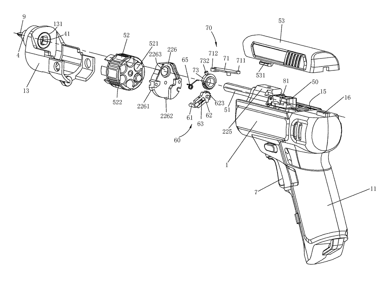
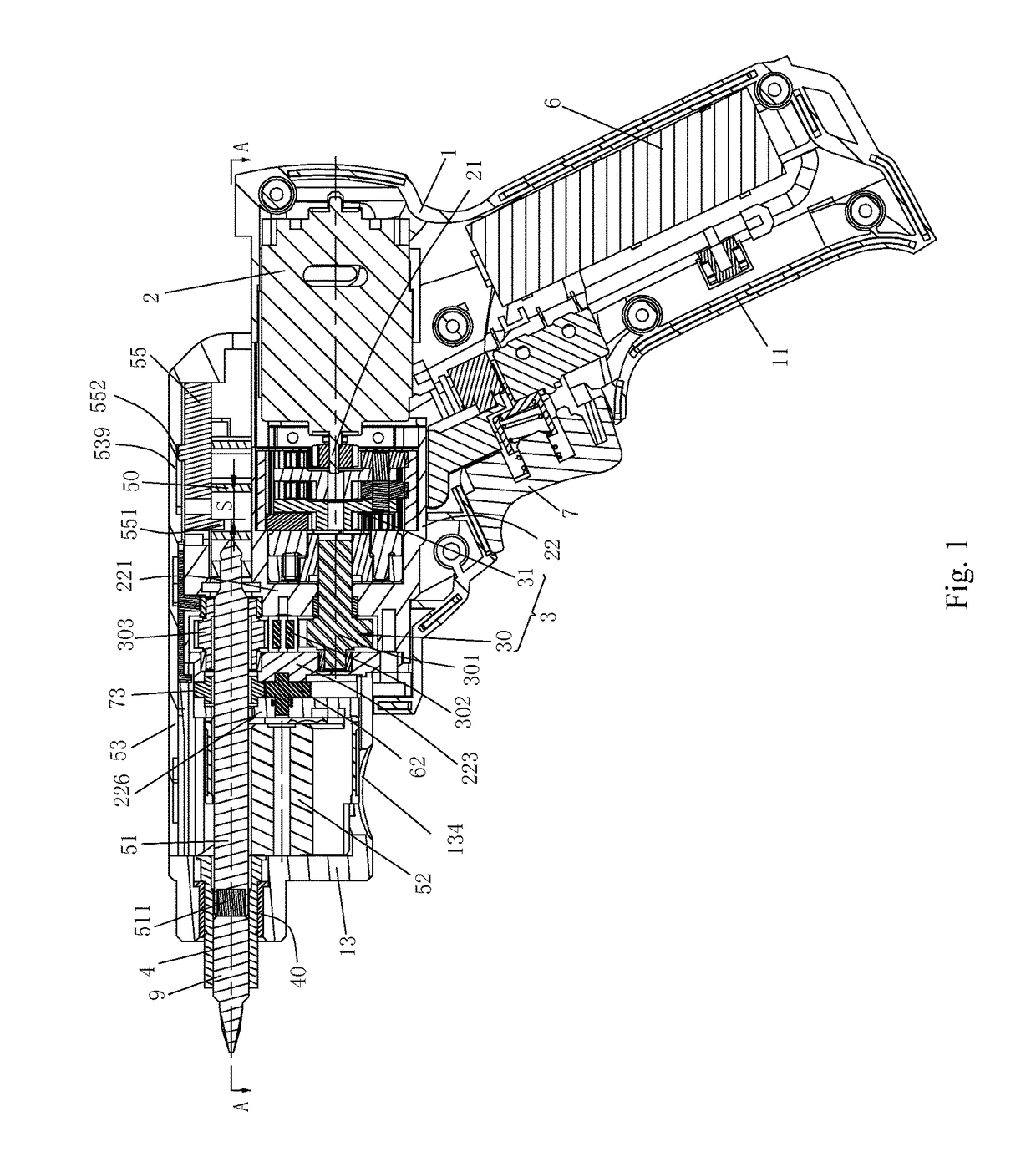
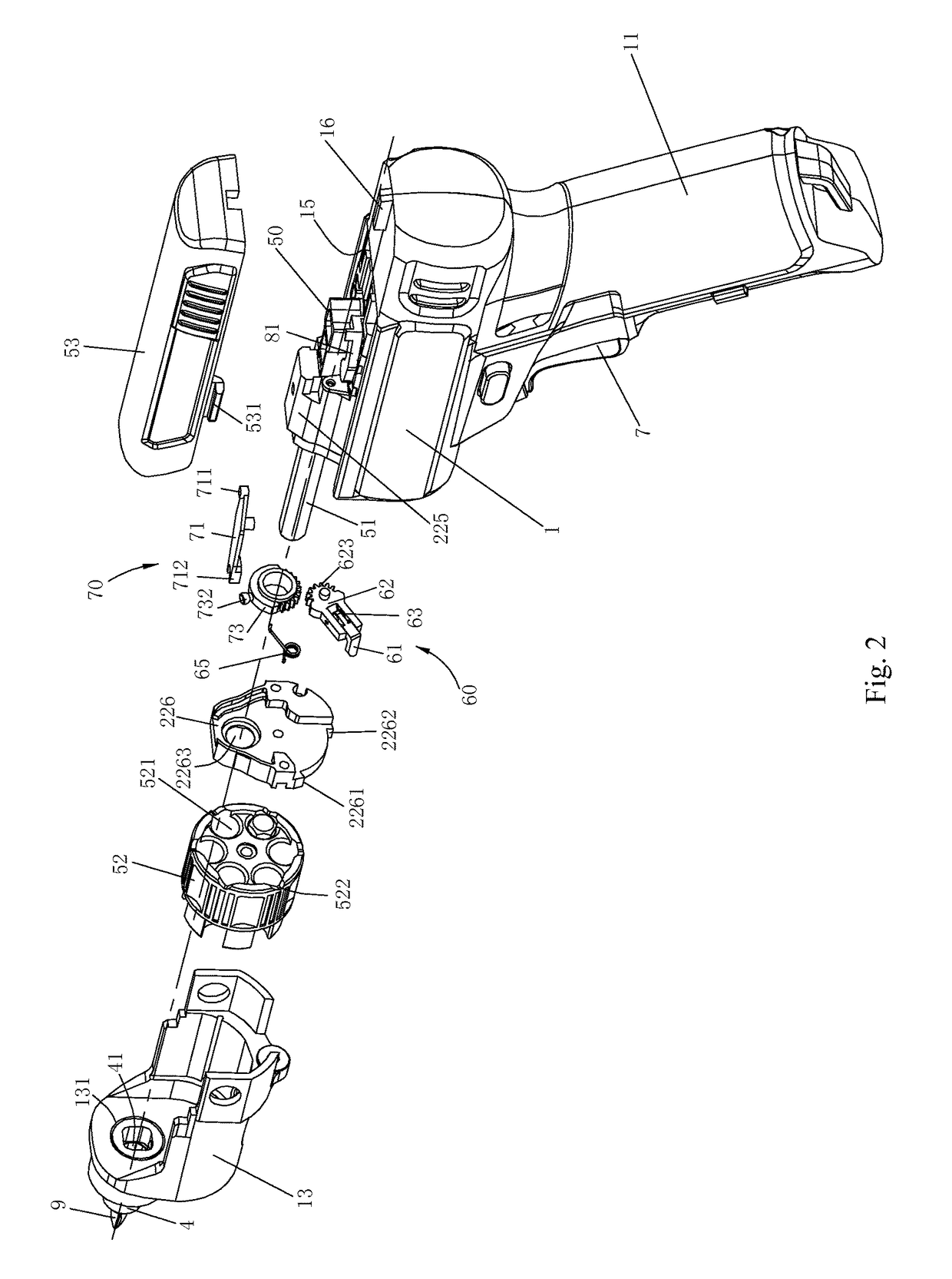
[0306]As shown in FIG. 1 to FIG. 16 is the first embodiment according to the present invention. The DC electric screwdriver comprises a housing 1, a motor 2, a battery 6, a transmission mechanism 3, a connecting member 51, a tool bit supporting assembly and an output shaft 4. The housing 1, formed by assembling two symmetrical semi-housings together with screws (not shown in the figures), has a horizontal component and a handle 11 arranged at an obtuse angle with the horizontal component. The present invention prefers to adopt an angle between 100 degrees to 130 degrees, which provi...