Ground potential operation non-bearing connection wire clamp

A non-load-bearing, continuous line technology, applied in the direction of electrical components, cable installation, overhead lines/cable equipment, etc., can solve the increasingly high requirements for power quality and power supply reliability of distribution lines, difficult operations, To avoid unnecessary economic and social losses, to facilitate installation and disassembly, and to facilitate installation and construction

Active Publication Date: 2013-12-18
JIANGSU ELECTRIC POWER CO +1
View PDF4 Cites 8 Cited by
  • Summary
  • Abstract
  • Description
  • Claims
  • Application Information

AI Technical Summary

Problems solved by technology

At present, the non-load-bearing splicing clamps such as parallel trench clamps, amp clamps, C-type clamps, and insulation piercing clamps commonly used on distribution lines did not consider the needs of live work when they were developed. Both require power outage construction, and the frequent power outage construction of distribution lines cannot meet the user's increasingly high requirements for power quality and power supply reliability, and bring unnecessary losses to economic and social development.
If the above-mentioned clamps need to be operated with ground potential insulating operating rods, it is necessary to temporarily develop targeted special tools, and these temporarily developed special tools have limitations, long working hours, and difficult operations, so it is difficult to be popularized
At present, with the improvement of insulation protection technology, the direct operation method of insulating bucket arm truck and insulating gloves is used to carry out related operations, but this operation method has relatively high requirements for the working environment such as roads and ground, such as places that cannot be reached by insulating bucket arm vehicles. It is not possible to complete the construction in this way

Method used


Image

  • Ground potential operation non-bearing connection wire clamp
  • Ground potential operation non-bearing connection wire clamp
  • Ground potential operation non-bearing connection wire clamp

Examples


Embodiment 1)

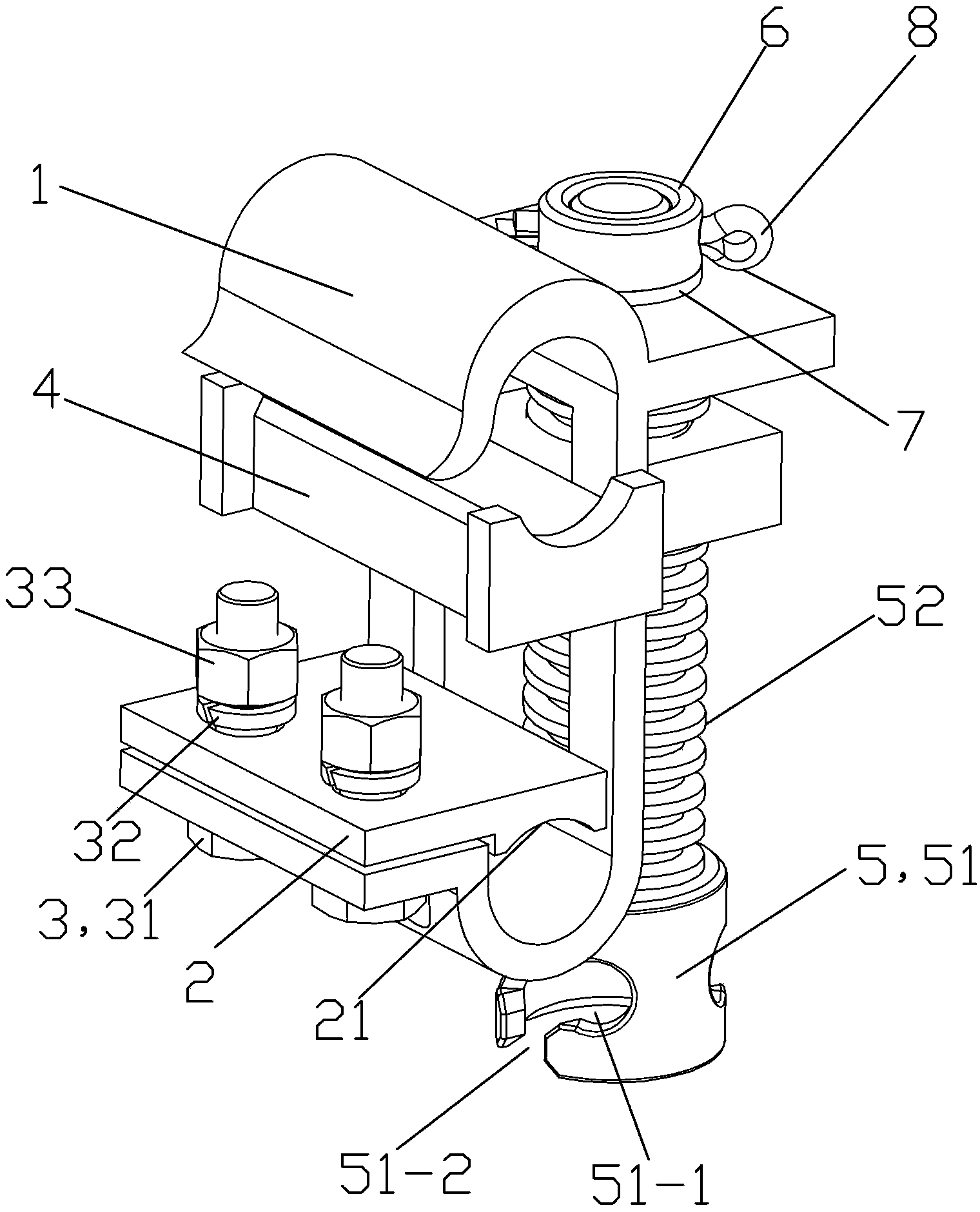
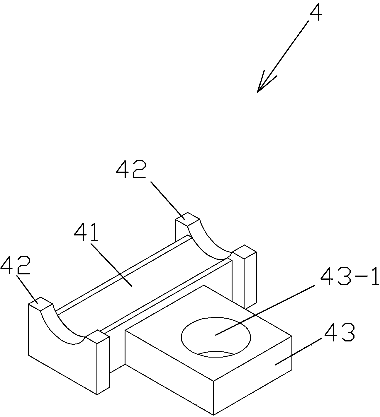
[0032] See Figure 1 to Figure 3 , the ground potential operation non-load-bearing connection clamp of this embodiment is mainly composed of a clamp main body 1, a drain line pressure plate 2, a bolt connection assembly 3, a busbar fastener 4, a driving screw 5, a guide sleeve 6, a sliding sleeve 7 and Shaft pin 8 forms.

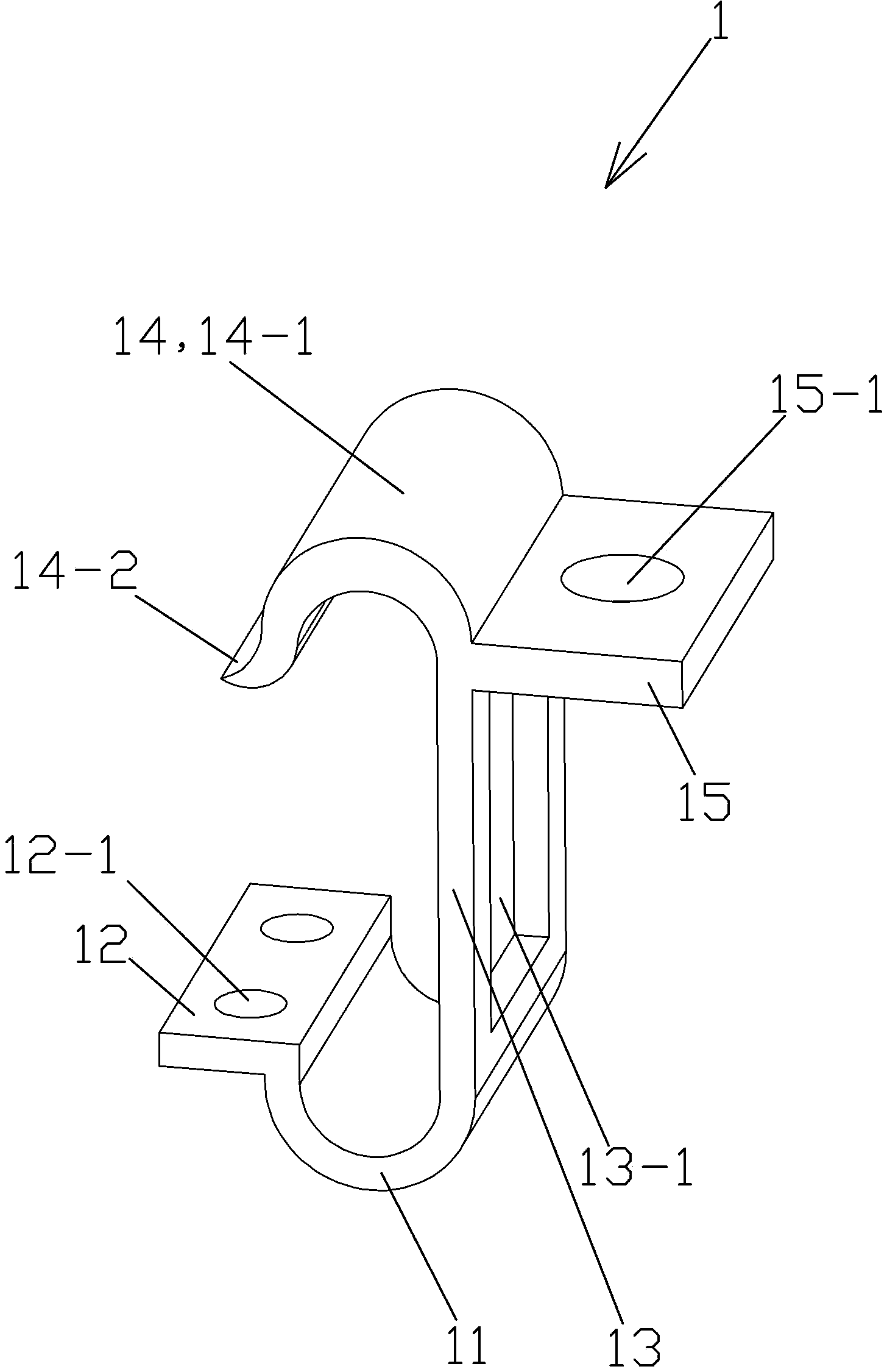
[0033] See figure 2 , The clamp main body 1 is an integral piece made of aluminum alloy. The clamp main body 1 is integrally composed of a drain wire mounting part 11 , a drain wire pressing plate connecting part 12 , an intermediate connecting part 13 , a bus bar clamping part 14 and a connecting ear plate 15 .

[0034] The drain wire installation part 11 is an arc-shaped plate body protruding downward. The drain line clamping plate connecting portion 12 is a rectangular plate body part arranged horizontally, and the draining wire clamping plate connecting portion 12 is provided with 2 circular through-holes up and down, as the bolt holes 12-1 for insta...


PUM


Abstract

The invention provides a ground potential operation non-bearing connection wire clamp. The ground potential operation non-bearing connection wire clamp comprises a wire clamp body, a drainage wire pressing plate, bolted connection assemblies, a bus fastener, a driving screw, a guide sleeve, a sliding sleeve and a shaft pin. The drainage wire pressing plate is in bolted connection with the wire clamp body through the bolted connection assemblies, the bus fastener is in threaded connection with the driving screw, and the sliding sleeve is fixedly installed on a connecting lug plate through a connecting through hole of the connecting lug plate of the wire clamp body in a vertical interference fit mode. The inner wall of the guide sleeve and the upper end of a thread driving column of the driving screw are in threaded connection and then connected in a pin joint mode through the shaft pin. The outer wall of the guide sleeve and the inner wall of the sliding sleeve can be connected in a sleeved and vertical sliding mode. The ground potential operation non-bearing connection wire clamp is simple in structure, low in cost, convenient to mount and demount, and high in working efficiency and applicability, time and labor are saved, construction can be directly conducted under the power-outage-free condition, and unnecessary economic and social losses caused by power outage construction can be effectively avoided.

Description

technical field [0001] The invention relates to a power-taking device in an overhead power distribution line, in particular to a non-load-bearing splicing clip that can be installed and disassembled by electrified ground potential operations. Background technique [0002] The non-load-bearing connection clamp for ground potential operation is a live lapping device for overhead distribution line branches, knife switches, switches and other drainage lines. At present, the non-load-bearing splicing clamps such as parallel trench clamps, amp clamps, C-type clamps, and insulation piercing clamps commonly used on distribution lines did not consider the needs of live work when they were developed. Both require power outage construction, and the frequent power outage construction of distribution lines cannot meet the user's increasingly high requirements for power quality and power supply reliability, and bring unnecessary losses to economic and social development. If the above-men...

Claims


Application Information

Patent Timeline
Patent Type & Authority Applications(China)
IPC IPC(8): H02G7/00H02G1/02
Inventor 殷洪海张金姬纪良王曙宁
Owner JIANGSU ELECTRIC POWER CO
Why Eureka
Try Eureka