
Assembling method and apparatus for assembly, and assembling method and apparatus for workpiece

a technology of assembling method and assembly method, which is applied in the direction of soldering apparatus, manufacturing tools,auxillary welding devices, etc., can solve the problems of poor work efficiency, inability to complete the work of setting the components on the workpiece support at the other work station, and a large amount of time for setting the components on the workpiece support. achieve the effect of preventing an increase in cost and high work efficiency

Active Publication Date: 2012-11-20
HONDA MOTOR CO LTD
View PDF6 Cites 9 Cited by
  • Summary
  • Abstract
  • Description
  • Claims
  • Application Information

AI Technical Summary

Benefits of technology

This approach reduces the need for multiple work stations, decreases assembly time, and enhances work efficiency by allowing continuous operation of welding robots, making the assembly line configuration more compact and cost-effective.

Problems solved by technology

Due to this the line configuration becomes large and thus the cost increases and in addition the amount of time required for loading / unloading and transport increases, resulting in poor work efficiency.
When a workpiece is composed of numbers of components, however, work for setting the components on a workpiece support requires a great amount of time.
Hence, even when welding and assembly of a workpiece by the welding robot is completed at one of the work stations, setting of a workpiece on a workpiece support at the other work station is not completed.
Accordingly, during this period, work by the welding robot goes into a non-operating state, thereby decreasing work efficiency.
Accordingly, the difference in the amount of time required for work between the two work stations is large, thereby significantly decreasing work efficiency.

Method used


Image

  • Assembling method and apparatus for assembly, and assembling method and apparatus for workpiece
  • Assembling method and apparatus for assembly, and assembling method and apparatus for workpiece
  • Assembling method and apparatus for assembly, and assembling method and apparatus for workpiece

Examples


Embodiment Construction

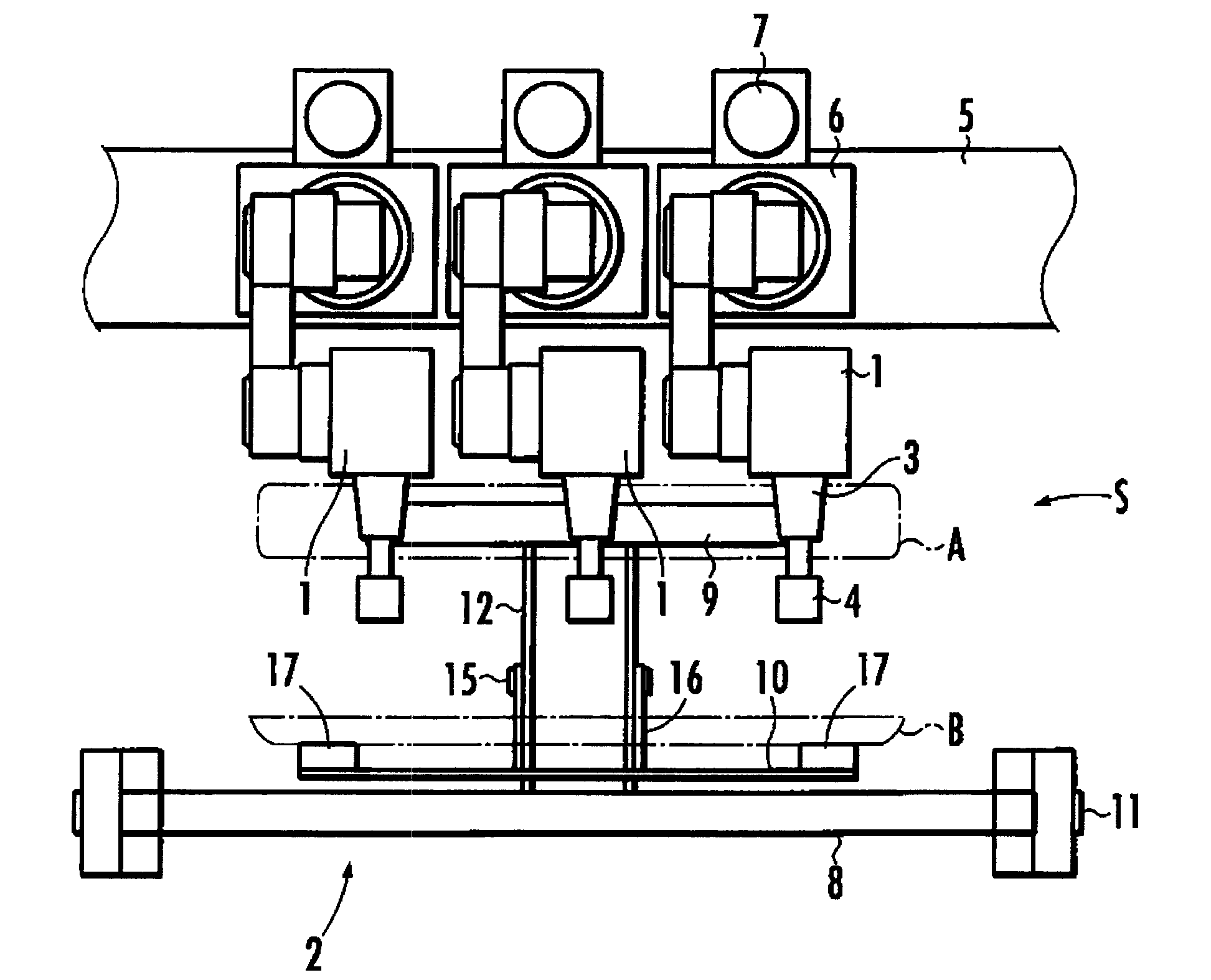
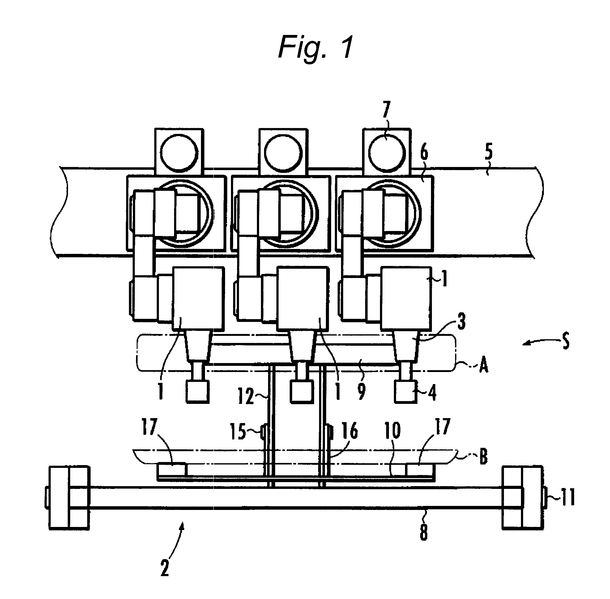
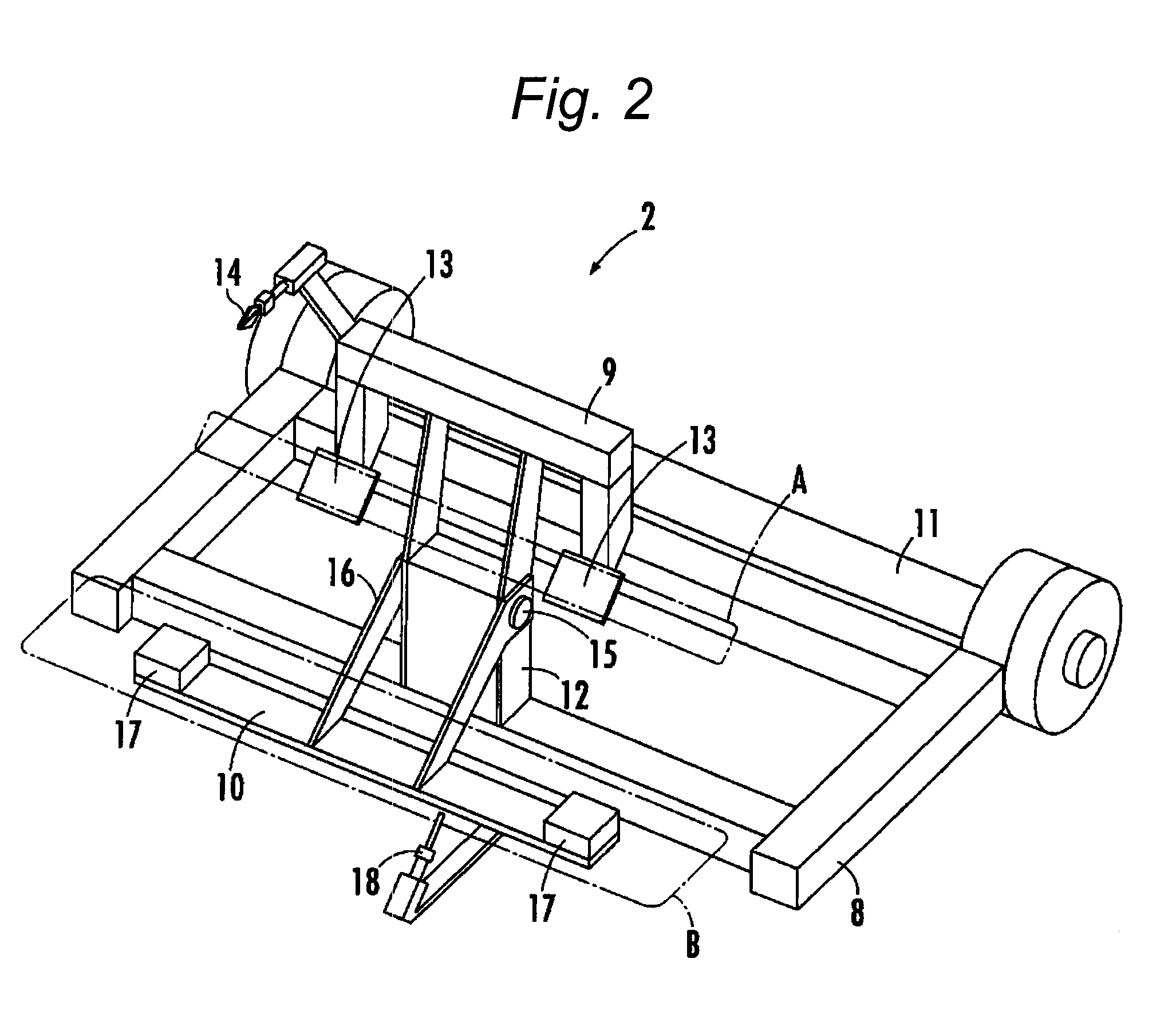
[0025]A first exemplary embodiment of the present invention will be described based on FIGS. 1 to 6B. FIG. 1 is a plan view showing an assembly apparatus according to the first exemplary embodiment, FIG. 2 is a perspective view showing a component holding unit according to the first exemplary embodiment, FIGS. 3 and 4 are illustrative views showing clamping units, and FIGS. 5A, 5B, 6A, and 6B are illustrative views of the operation of the component holding unit.

[0026]An assembly apparatus according to the first exemplary embodiment welds and assembles, for example, a plurality of components of an assembly such as a dashboard assembly which is mounted on a vehicle. As shown in FIG. 1, the assembly apparatus includes a plurality of welding robots 1 (assembly work units) and a component holding unit 2 that holds a plurality of components composing assemblies, in an assembly work area S for the welding robots 1.

[0027]Each welding robot 1 includes an articulated arm 3 and a welding gun 4...


PUM

PropertyMeasurementUnit
timeaaaaaaaaaa
shapeaaaaaaaaaa

Abstract

A first holding frame of a component holding unit is allowed to hold a plurality of components composing a first assembly and a second holding frame of the component holding unit is allowed to hold a plurality of components composing a second assembly which is to be mounted on the first assembly. The first assembly held onto the first holding frame and the second assembly held onto the second holding frame are assembled by an assembly work unit. The second holding frame is allowed to reciprocate towards the first holding frame to pass the second assembly from the second holding, frame to the first holding frame. Thereafter, the first assembly and the second assembly which are held onto the first holding frame are assembled and coupled together by the assembly work unit.

Description

[0001]This application claims priority from Japanese Patent Application No. 2008-206234, filed on Aug. 8, 2008, and Japanese Patent Application No. 2008-206235, filed on Aug. 8, 2008, the entire contents of which are hereby incorporated by reference.FIELD OF THE INVENTION[0002]The present invention relates to an assembling method and an assembling apparatus for an assembly from a plurality of components.[0003]The present invention further relates to an assembling method and an assembling apparatus for a workpiece.DESCRIPTION OF RELATED ART[0004]An Japanese Laid-Open Patent Publication No. H05-169335 (Hereinafter, Patent Document 1) discloses an related art apparatus in which a rear fender which is a mounting component of a vehicle is supported by a support member and loaded in a welding position and a component is welded to the rear fender by a welding robot, whereby a rear fender assembly is assembled. By holding a rear fender and an attachment component thereof in an assembling ar...

Claims


Application Information

Patent Timeline
Patent Type & Authority Patents(United States)
IPC IPC(8): B21D39/03B25B27/14
CPCB23K11/11B23K37/047B23K2201/006Y10T29/53978Y10T29/49826Y10T29/49829B23K2201/18B23K2101/006B23K2101/18
Inventor TOBITA, TADASHIYOSHINO, SHINJITSUTSUMI, KENJIROSATO, MASASHI
Owner HONDA MOTOR CO LTD
Learn More