
Original fabric pitch feed mechanism of original fabric manufacturing device for electrochemical element

a manufacturing device and original fabric technology, applied in mechanical control devices, capacitor manufacturing, sustainable manufacturing/processing, etc., can solve the problems of abnormal temperature of the battery, infrequent fire, slippage at the non-formed electrode parts, etc., and achieve high work efficiency

Active Publication Date: 2012-09-06
O M C
View PDF2 Cites 9 Cited by
  • Summary
  • Abstract
  • Description
  • Claims
  • Application Information

AI Technical Summary

Benefits of technology

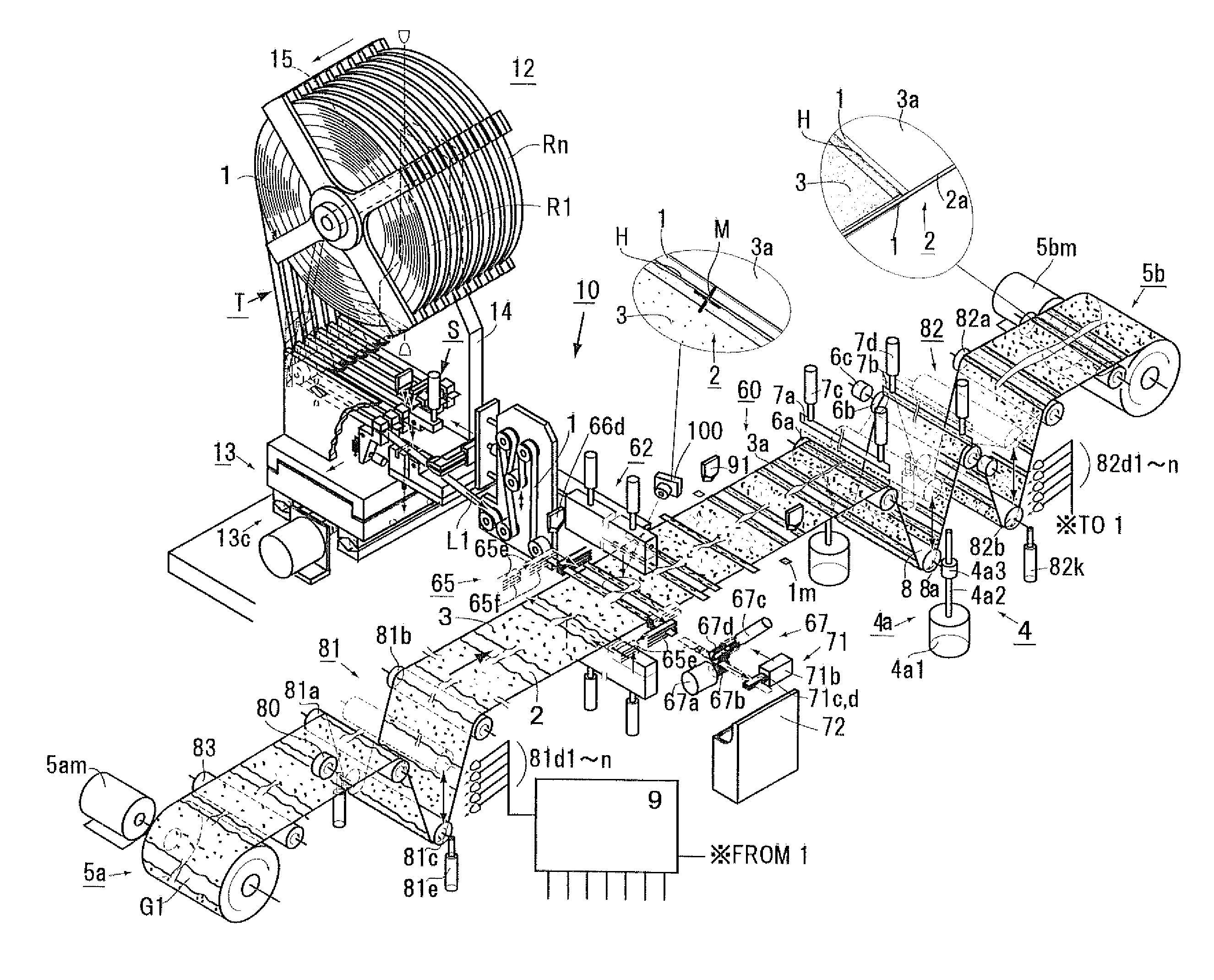
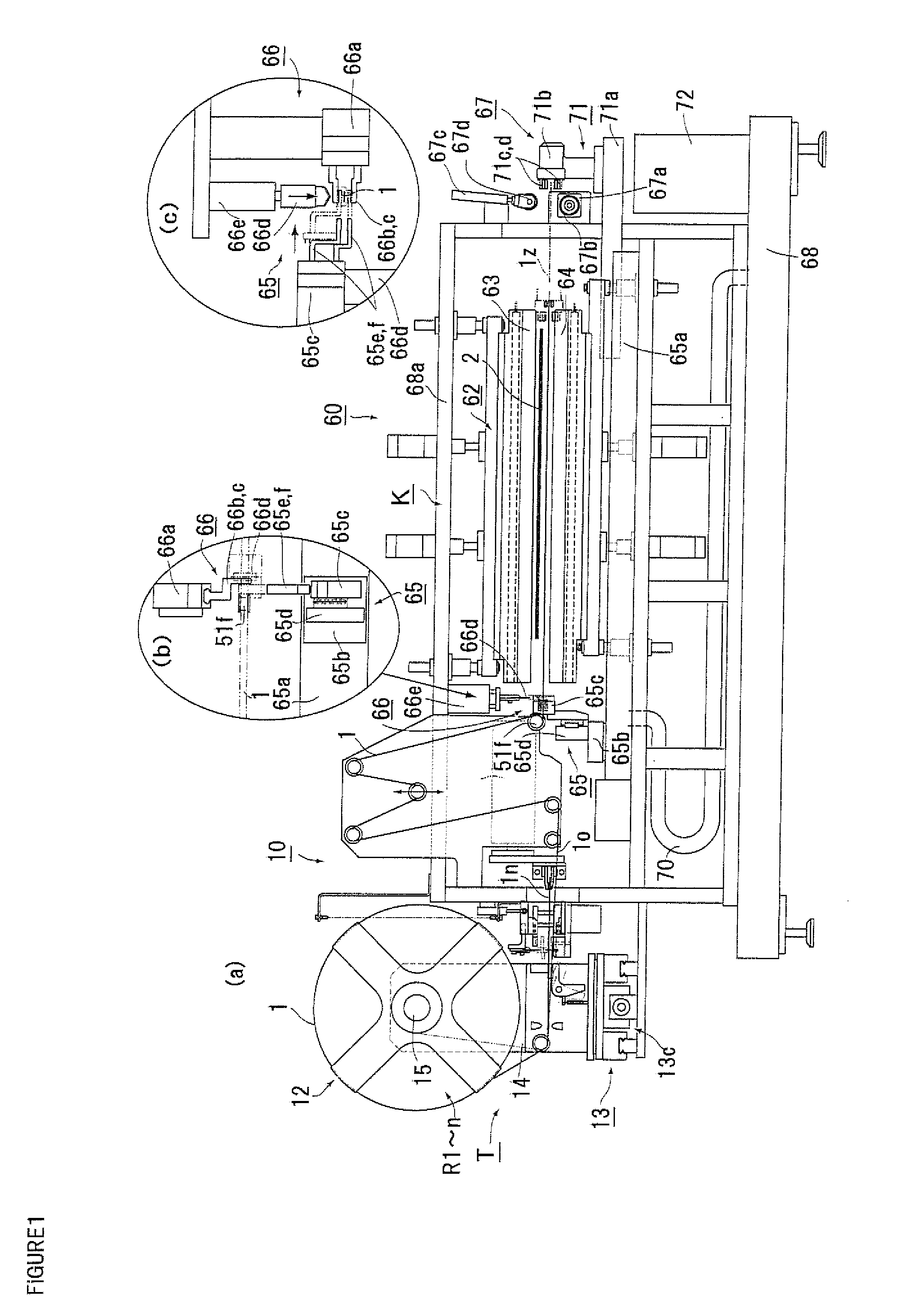
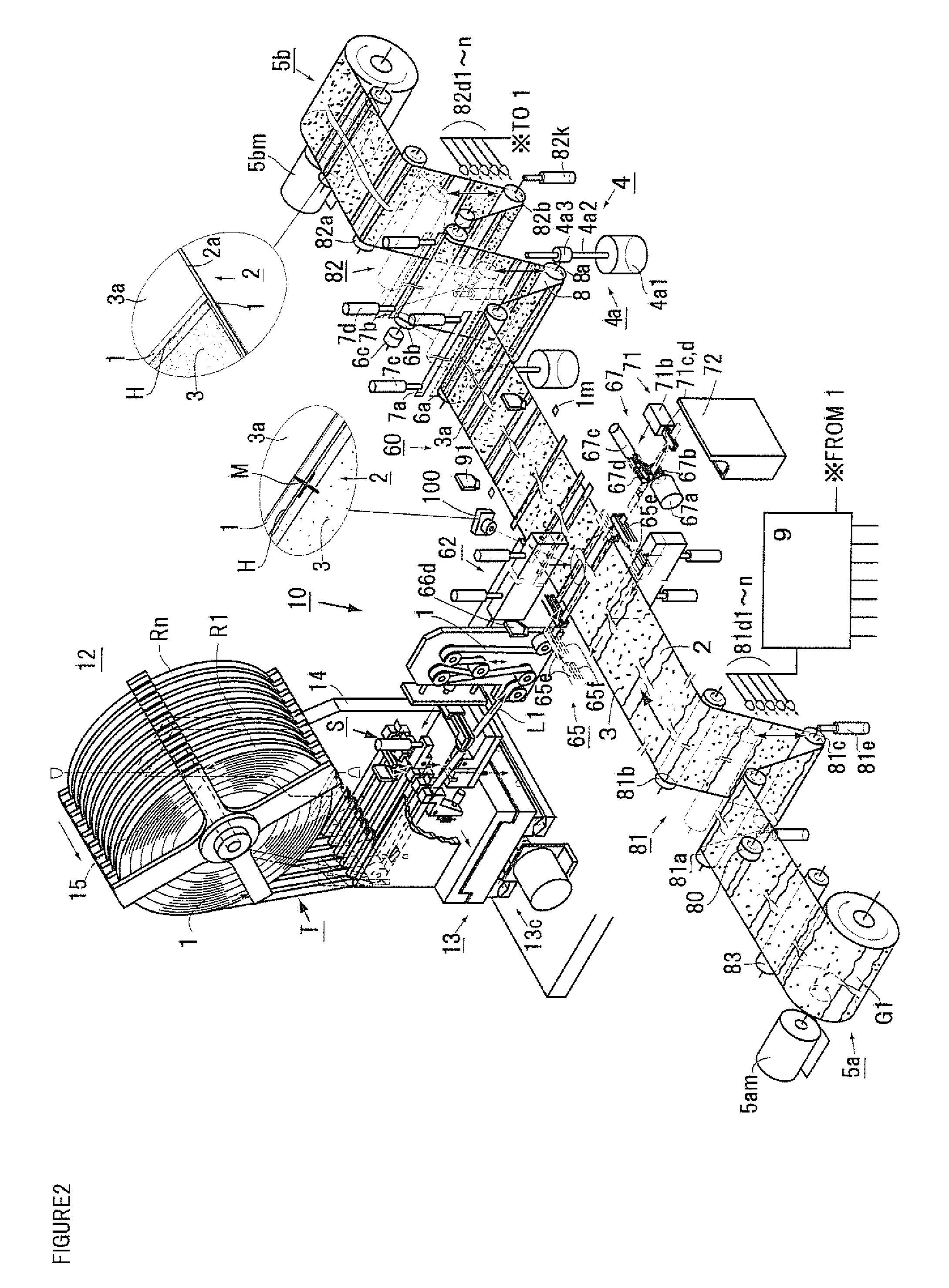
[0015]In the present invention, in order to draw the original fabric (2) by a predetermined length, the take-up side contacting / separating member (7b) presses against the original fabric take-up side roller (6b) to sandwich and fix the original fabric (2) therebetween, and in a state where the feed side contacting / separating member (7a) is moved away from the feed side roller (6a), the pitch feed roller (8) presses against the original fabric (2) to draw the original fabric (2) only from the feed side roller (6a) side. Thus, a feed amount of the original fabric (2) that is forcedly drawn from the upstream side by moving the pitch feed roller (8) is uniquely determined by a movement amount of one movement of the pitch feed roller (8) even when the original fabric (2) has an uneven surface.
[0016]In such a case, when the one-way clutch (6c) which rotates only in the transfer direction is installed on the bearing rotation portion of the original fabric take-up side roller (6b), reverse rotation of the original fabric take-up side roller (6b) due to movement of the pitch feed roller (8) to press the original fabric (2) can completely be prevented. Thus, due to a combination of the prevention and a fixing force of the take-up side contacting / separating member (7b) that presses against the original fabric take-up side roller (6b) to hold the original fabric (2) therebetween, the original fabric (2) is not at all drawn from the original fabric take-up side roller (6b) side, and high-speed pitch feed is also enabled.
[0017]Further, when the control section (9) is provided which detects a position where the original fabric (2) is fed by the pitch feed roller (8) and which controls a movement amount of the pitch feed roller (8) on the basis of a result of the detection to control a feed amount, pitch feed is enabled while fine correction is performed for each pitch feed, and the long original fabric (2) can be drawn in an accurate feed amount at a high speed throughout the original fabric (2). Thus, the insulating tape (1) can be attached to an appropriate location at high work efficiency.

Problems solved by technology

Thus, the temperature of the battery abnormally increases, and fire infrequently occurs in terrible cases.
However, the portions of electrodes that are formed on the front and back of the original fabric are thick as compared to electrode non-formed portions, and due to the steps, slippage occurs at the electrode non-formed portions.
Thus, accurate pitch feed cannot be performed, and the feed speed is not sufficient.
However, when an electrode sheet is fed solely with the elevating roller, high-speed rough feed and subsequent low-speed accurate feed have to be combined since the electrode sheet is not assuredly fixed.
Thus, a transfer method is complicated, and the efficiency is poor in terms of work efficiency since the two types of feeds have to be combined.

Method used


Image

  • Original fabric pitch feed mechanism of original fabric manufacturing device for electrochemical element
  • Original fabric pitch feed mechanism of original fabric manufacturing device for electrochemical element
  • Original fabric pitch feed mechanism of original fabric manufacturing device for electrochemical element

Examples


Embodiment Construction

[0022]The following will describe one embodiment of the present invention based on the drawings. An original fabric manufacturing device (60) is a device that pitch-feeds an original fabric (2) at predetermined intervals and accurately attaches an insulating tape (1) for electrochemical elements to boundary portions (H) between electrodes (3) provided on the original fabric (2) and electrode non-formed portions (3a). The original fabric manufacturing device (60) generally includes an original fabric feed section (5a), an original fabric take-up section (5b), an original fabric pitch feed mechanism (4), a compression-bonding mechanism section (62) for the insulating tape (1), an automatic feeder (10) for the insulating tape (1), and a control section (9).

[0023]In the original fabric (2) used in the present invention, in the case of a positive electrode, a positive electrode coating material, which is prepared by dispersing and mixing a lithium-transition metal composite oxide such as...


PUM

PropertyMeasurementUnit
speedaaaaaaaaaa
shapeaaaaaaaaaa
viscousaaaaaaaaaa

Abstract

Provided is a pitch feed mechanism which is capable of performing an accurate, high-speed pitch feed of an original fabric having unevenness on a surface thereof in a sticking operation of an insulating tape. The original fabric pitch feed mechanism that is provided on a downstream side of an insulating tape sticking process region in a long original fabric, and performs the pitch feeding of the original fabric in one direction in accordance with a boundary part, the original fabric pitch feed mechanism being characterized by comprising a feed side roller, an original fabric take-up side roller, a feed side contact and separate member, a take-up side contact and separate member, and a pitch feed roller, which is disposed between the feed side roller and the original fabric take-up side roller, and pulls out, when the feed side contact and separate member is separated from the feed side roller, and the take-up side contact and separate member is in contact with the original fabric take-up side roller to fix the original fabric with the original fabric disposed therebetween, the original fabric by a predetermined size from the feed side roller side by pressing the original fabric that is extended between the feed side roller and the original fabric take-up side roller.

Description

TECHNICAL FIELD[0001]The present invention relates to an original fabric pitch feed mechanism that can accurately pitch-feed, at a high speed, an original fabric for electrochemical elements, such as an original fabric for rolled capacitors or an original fabric for lithium batteries, on which electrodes such as positive electrodes or negative electrodes are applied at equal intervals.BACKGROUND ART[0002]At present, as environmental countermeasures, secondary batteries such as high-capacity lithium-ion batteries have attracted a lot of attention as power supplies for electric vehicles, power-driven engines, and electronic devices. When a lithium-ion battery is taken as an example, an electrode in which a positive electrode active material is applied to a band-shaped positive electrode current collector formed from aluminum foil is used as its positive electrode, and an electrode in which a negative electrode active material is applied to a band-shaped negative electrode current coll...

Claims


Application Information

Patent Timeline
Patent Type & Authority Applications(United States)
IPC IPC(8): B32B38/18B32B41/00H01M4/04H01G13/00H01M4/1391H01M4/1393
CPCH01G11/26H01G13/00H01G13/02Y02E60/13H01M4/13H01M10/052Y02E60/122H01M4/0404Y02E60/10Y02P70/50
Inventor WATANABE, SHINJI
Owner O M C
Learn More