Safety valve

a safety valve and valve body technology, applied in the field of valves, can solve the problems of conventional safety valves, mechanical or electrical failure of single components, and a high vacuum level, and achieve the effect of small volume and low manufacturing cos

Inactive Publication Date: 2016-07-14
KONINKLJIJKE PHILIPS NV
View PDF6 Cites 2 Cited by
  • Summary
  • Abstract
  • Description
  • Claims
  • Application Information

AI Technical Summary

Benefits of technology

[0019]A particular advantage of the present invention is that depending on the pressure differences between the first and the second system the functionality of a safety valve can be realized. A medium can either enter the valve through the first connector opening, pass through the flow path opening and leave the valve through the second connector opening, or enter the valve through the second connector opening path through the flow path opening and leave the valve through the first connector opening. The flow path opening therein has the key role to allow the medium to flow or to block the flow path depending on the state of the valve.
[0020]According to one embodiment of the present invention, the deformable dome-shaped structure is deformed and the flow path opening is not connected to the contact element if the pressure difference between the first system and the second system is above a pressure release threshold and the deformable dome-shaped structure is in its original dome-shape and the flow path opening is in contact with the contact element if the pressure difference between the first system and the second system is below a pressure hold threshold.
[0021]Thus, according to this embodiment, the deformable dome-shaped structure is caused to be deformed, when a pressure difference between the first and the second system occurs. This deformable dome-shaped structure can only hold its original dome-shaped form if the force, i.e. the pressure, applied to it is below a certain pressure threshold, i.e. a pressure hold threshold. If the pressure diff...

Problems solved by technology

Depending on the type of the used pump, it is possible that the pump generates a too high vacuum level causing harm or injury to the user.
Possible causes therefor may be mechanical or electrical failure of single components, e.g. the pump or a solenoid valve.
However, conventional safety valves often have the problem that they open proportionally to ...

Method used


Image

  • Safety valve
  • Safety valve
  • Safety valve

Examples


Embodiment Construction

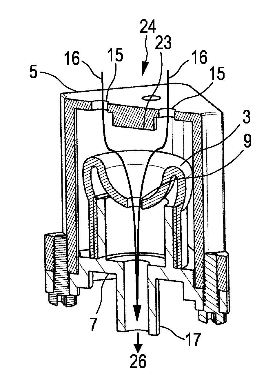
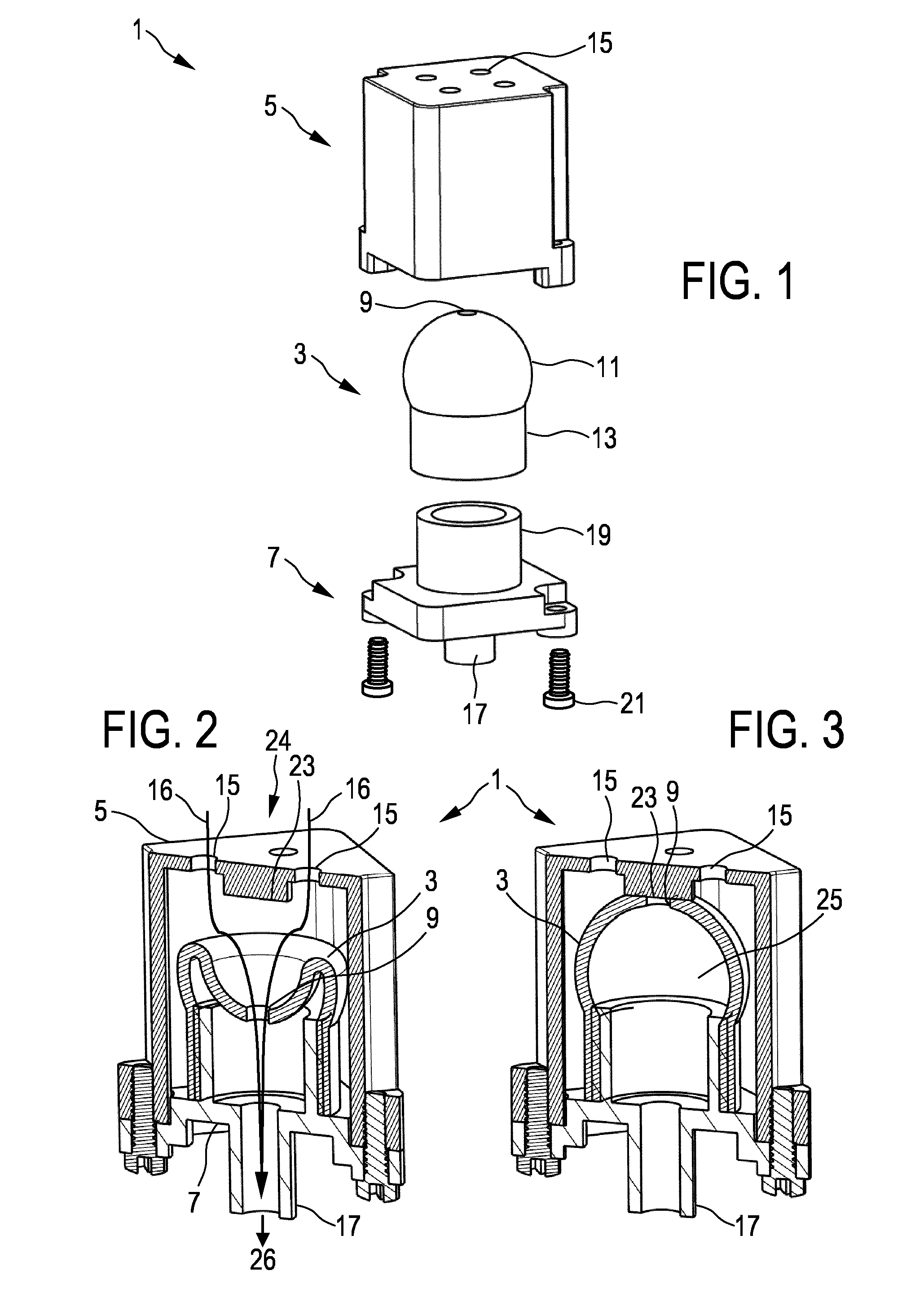
[0045]In FIG. 1 there is illustrated a valve 1 according to the present invention. The valve 1 comprises a deformable dome-shaped structure 3, a valve cover 5 and a valve base 7. In the illustrated example, the deformable dome-shaped structure 3 includes a flow path opening 9 arranged in the zenith of a hemisphere part 11 of the deformable dome-shaped structure 3. The structure 3 further comprises a cylinder part 13 having a diameter smaller than the diameter of the hemisphere part 11. The valve cover 5 includes a first connector opening 15 being represented by four venting holes arranged in a square on the upper side of the valve cover. The illustrated exploded view does not show the contact element. The valve base 7 includes a second connector opening 17 being represented by a cylinder-shaped system connection appendix. The second connector opening 17, respectively the cylinder-shaped system connection appendix, is formed to provide a support structure 19 for supporting the cylind...


PUM


Abstract

The present invention relates to a valve (1) for controlling the flow of a medium from a first system (24) to a second system (26) comprising a deformable dome-shaped structure (3) forming a reservoir (25) and including a flow path opening (9), a valve cover (5) including a first connector opening (15) to connect the valve (1) to the first system (24) and a contact element (23) for interacting with the flow path opening (9) to open and close it and a valve base (7) being airtightly connected to the valve cover (5) and to the dome-shaped structure (3) and including a second connector opening (17) to connect the valve (1) to the second system (26) and being coupled to the reservoir (25) The deformable dome-shaped structure (3) is configured such that in an open state of the valve (1) the deformable dome-shaped structure (3) is deformed and the flow path opening (9) is not connected to the contact element (23) to allow a medium to flow from the first system (24) to the second system (26) through the first (15) and second (17) connector openings and the flow path opening (9) and in a closed state of the valve (1) the deformable dome-shaped structure (3) is in its original dome shape and the flow path opening (9) is connected to the contact element (23) and thus closed. The present invention further relates to a pump device (47) and a breast pump device (41) including a valve (1) as described above.

Description

FIELD OF THE INVENTION[0001]The present invention relates to a valve for controlling the flow of a medium from a first system to a second system. The present invention further relates to a pump device and to a breast pump device comprising a valve.BACKGROUND OF THE INVENTION[0002]Safety valve mechanisms usually refer to mechanical or electrical components allowing to automatically release a medium from any kind of pressure vessel or other system when the pressure exceeds a preset limit. By releasing the pressure, the pressure vessel or system can be protected from being damaged or even from exploding. Further, any equipment or person being connected to this pressure vessel or system can also be protected from being harmed because of a too high or too low pressure.[0003]Breast pump devices are usually used by lactating women for extracting milk from their breasts. Such breast pump devices may be manual devices powered by hand or foot movements or mains- or battery-powered electrical ...

Claims


Application Information

Patent Timeline
IPC IPC(8): A61M1/06G05D16/06F16K15/14F16K24/06A61M1/00A61M39/22
CPCA61M1/062A61M1/0035A61M1/0037G05D16/0641F16K15/145F16K24/06A61M39/22A61M1/06A61M1/742A61M1/75A61M1/06935A61M1/743
Inventor PAN, YI BING
Owner KONINKLJIJKE PHILIPS NV
Why Eureka
Try Eureka