
Needlefree valve device

a valve device and needle-free technology, applied in the field of needle-free medical valve devices, can solve the problems of high manufacturing cost and achieve the effect of expanding flexibility

Active Publication Date: 2016-07-14
CEDIC
View PDF58 Cites 5 Cited by
  • Summary
  • Abstract
  • Description
  • Claims
  • Application Information

AI Technical Summary

Benefits of technology

The valve device described in this patent is simple in structure and easy to use. It is made up of three main components that can be produced using known technologies such as injection molding. The device has a flexible and elastic material that compresses to prevent fluid from flowing through the passageway when in the closed position. The locking mechanism is a latch and recess that secure the device in the open or closed position. The sealing component is made of silicone rubber, which is commonly used in medical applications. The valve device can be used in various fields such as medical connectors or hydraulic connectors. The technical effects of this patent are a simplified structure, easy handling, and improved safety and reliability.

Problems solved by technology

The structures of these connectors are complex, thus leading to high manufacturing costs.

Method used


Image

  • Needlefree valve device
  • Needlefree valve device
  • Needlefree valve device

Examples


first embodiment

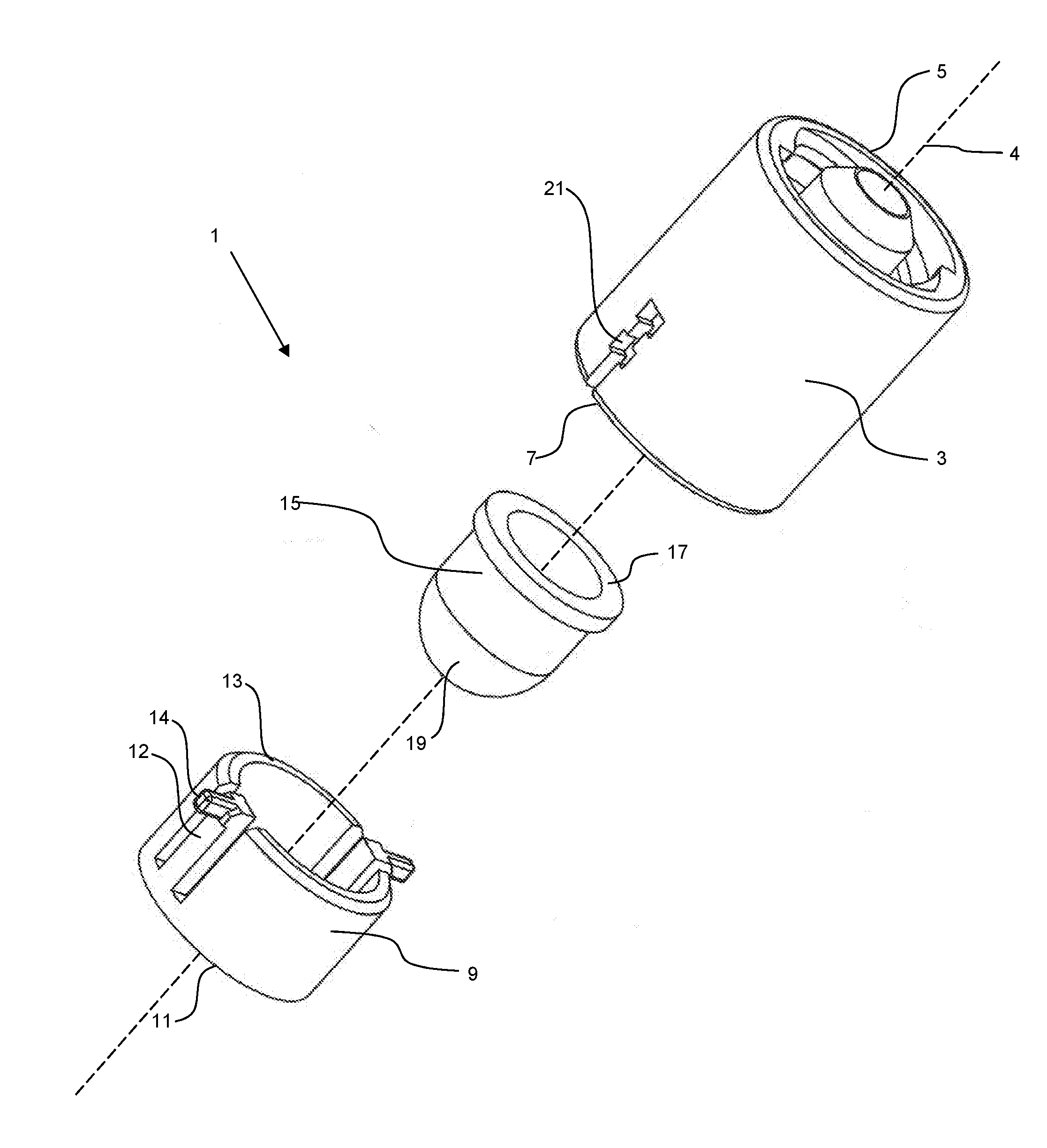
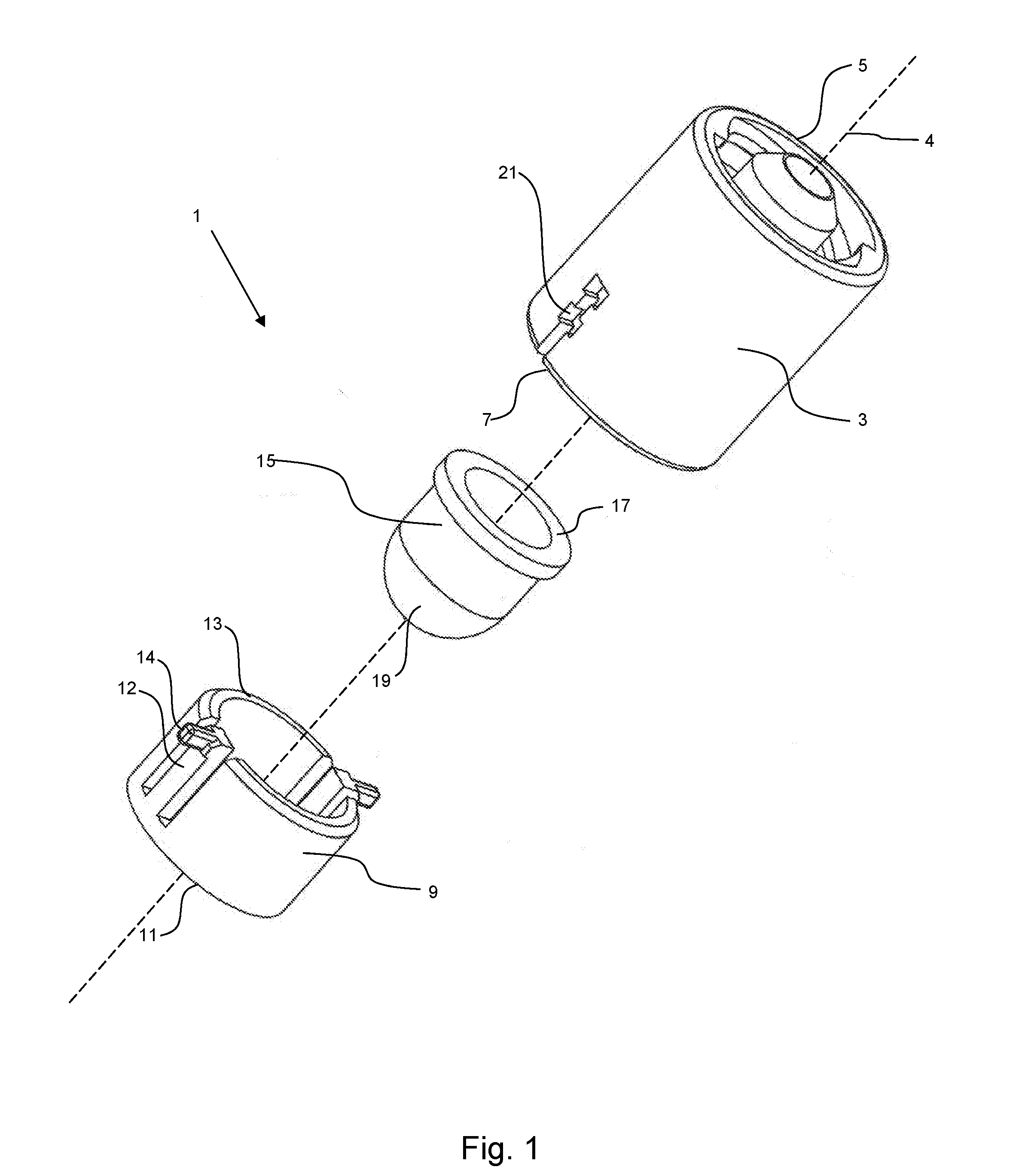
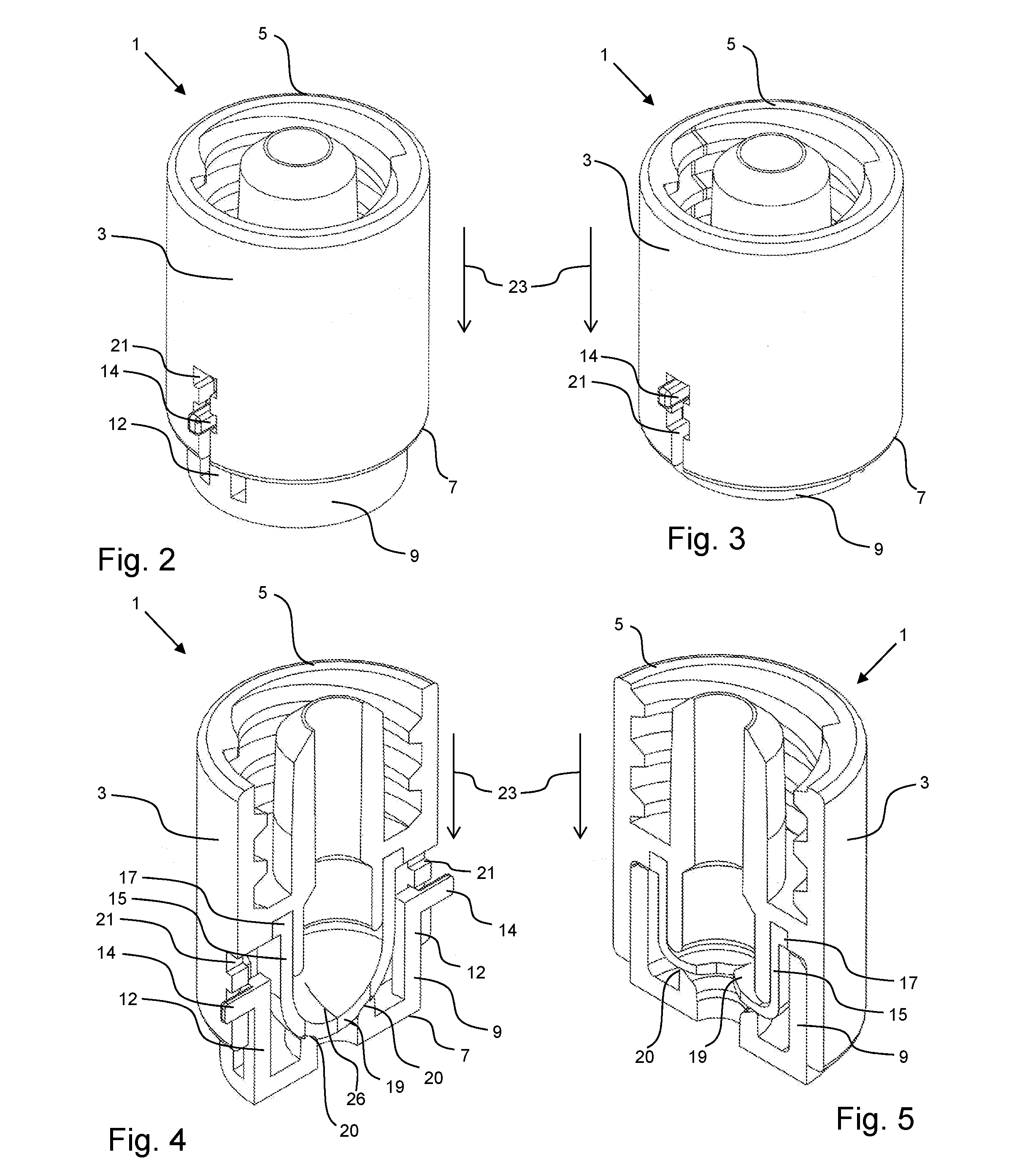
[0046]The latches 12 with their grip protrusions 14 are adapted to be inserted into the recesses 21 on first component 3 when the valve device 1 according the invention is operable. In the following, the function of this first embodiment of the valve device will be explained in more detail with respect to FIGS. 2 to 5.

[0047]FIG. 2 shows a perspective view of the first embodiment of valve device 1 in the closed configuration. Second component 9 is connected to first component 3 with the sealing component 15 arranged in between (not shown). In the closed configuration depicted in FIG. 2 the latches 12 with the grip protrusion 14 are engaged with the lower portion of recess 21 in the outer surface of first component 3. It must be noted that the structure of the embodiment depicted in FIG. 2 comprises a short portion of second component 9 extending from the valve end 7 of first component 3. This portion may have other dimensions depending on the type of connection at connector end 11 of...

second embodiment

[0052]Recess 21 of first component 3 comprises a substantially rectangular configuration with a larger extension in the circumferential direction than in the axial direction parallel to the opening axis 23. Approximately in the middle of the longitudinal extension of recess 21 there is a locking arm 22 extending in a circumferential direction into recess 21 giving recess 21 a U-shape wherein the “U” is rotated by 90° with respect to the valve axis 4. In the embodiment shown as the second embodiment in FIGS. 6 to 10 the locking arm 22 extends from the right side wall in the outer surface of first component 3. The reason for this arrangement of locking arm 22 within recess 21 will become clear with respect to the detailed description of FIGS. 7 to 10 below.

[0053]The difference between the first and the second embodiment with respect to the latch 12 is that in the second embodiment of FIG. 6 the free end of latch 12 near the valve end 13 does not comprise a grip protrusion 16 as in the...

third embodiment

[0064]The other possibility of movement for latch 12 out of the closed configuration depicted in FIG. 12 is the general opening movement of the valve in the opening direction indicated by arrow 23 which means that the engagement of the latch 12 with the locking arm 22 is released and the first component 3 is moved towards second component 9 until finally the position depicted in FIG. 14 is reached. In this open configuration, the protrusion 16 of latch 12 is in engagement with the upper portion of locking arm 22 and generally latch 12 is located in the right half of recess 21. From this open position in FIG. 14, a rotational movement in the circumferential direction of the first component 3 with respect to the second component 9 leads to the configuration depicted in FIG. 15, i. e. the engagement of latch 12 with locking arm 22 is released and latch 12 is now in the upper left corner of recess 21 when looking at FIG. 15. This configuration is an unstable configuration in the sense t...


PUM


Abstract

Needle free valve device (1) for controlling the flow of fluid in a pathway, the device (1) being operable in a closed and in an open configuration and comprising a first component (3), a second component (9),a locking means configured to selectively engage the first component (3) with the second component (9) in the open configuration when the first component (3) is displaced in an opening direction (23) along a valve axis toward the second component (9) or in the closed configuration when the first component (3) is displaced against the opening direction (23) away from the second component (9), and a sealing component (15) having a resilient portion (19), the resilient portion (19) comprising at least one slit (26) and engaging the second component (9) to provide a seal in the closed configuration, wherein the resilient portion (19) is adapted to move, buckle or flex to enable fluid flow through the at least one slit (26) upon application of a mechanical force of the second component (9) on the resilient portion (19) against the opening direction (23) when assuming the open configuration, and wherein the resilient portion (19) is adapted to return the valve device (1) to the closed configuration when the mechanical force is no longer applied.

Description

CROSS-REFERENCE TO RELATED APPLICATION[0001]The present application is a U.S. national phase entry of pending International Patent Application No. PCT / EP2013 / 067361, international filing date Aug. 21, 2013, the contents of which are incorporated by reference in its entirety.FIELD OF THE INVENTION[0002]The present invention generally relates to valve devices of the type used in the handling and administration of fluids, and more particularly to a needlefree medical valve device adapted to be used in any type of tube connection such as between the different kinds of ports and syringes, catheters, pumps, or the like which are used in the administration of all kinds of fluids. Examples of such administration are intravenous, enteral or parenteral delivery of fluids to or from a body.BACKGROUND OF THE INVENTION[0003]Needlefree valve connectors are known in the art reducing the accidental needle stick exposure to medical personnel, reducing the risk of contamination and patient infection ...

Claims


Application Information

Patent Timeline
Patent Type & Authority Applications(United States)
IPC IPC(8): A61M39/26A61M39/10
CPCA61M39/26A61M2039/1083A61M2039/1088A61M39/1011A61M39/045A61M39/22A61M2039/267
Inventor GAGLIARDONI, GIANCARLOMIJERS, JAN WILLEM MARINUS
Owner CEDIC
Learn More