Pneumatic tire

a technology of pneumatic tires and pneumatic wheels, applied in the field of pneumatic tires, can solve the problems of excessive distortion of rubber and cords, and achieve the effect of reducing rolling resistance and quickly determining with eas

Active Publication Date: 2016-07-14
SUMITOMO RUBBER IND LTD
View PDF3 Cites 3 Cited by
  • Summary
  • Abstract
  • Description
  • Claims
  • Application Information

AI Technical Summary

Benefits of technology

[0039]A pneumatic tire according to the present invention allows achievement of reduction of rolling resistance without taking influence on a mass into consideration.
[0040]Further, in the method for determining a carcass profile of a tire according to the present invention, in order to extend a series of tire widths for one aspect ratio, carcass profiles for the different tire widths can be quickly determined with ease.

Problems solved by technology

As a result, the carcass profile for a tire having a certain tire width greatly changes between before inflation and after inflation, so that excess distortion may be generated in rubber and cords.

Method used


Image

  • Pneumatic tire
  • Pneumatic tire
  • Pneumatic tire

Examples


first embodiment

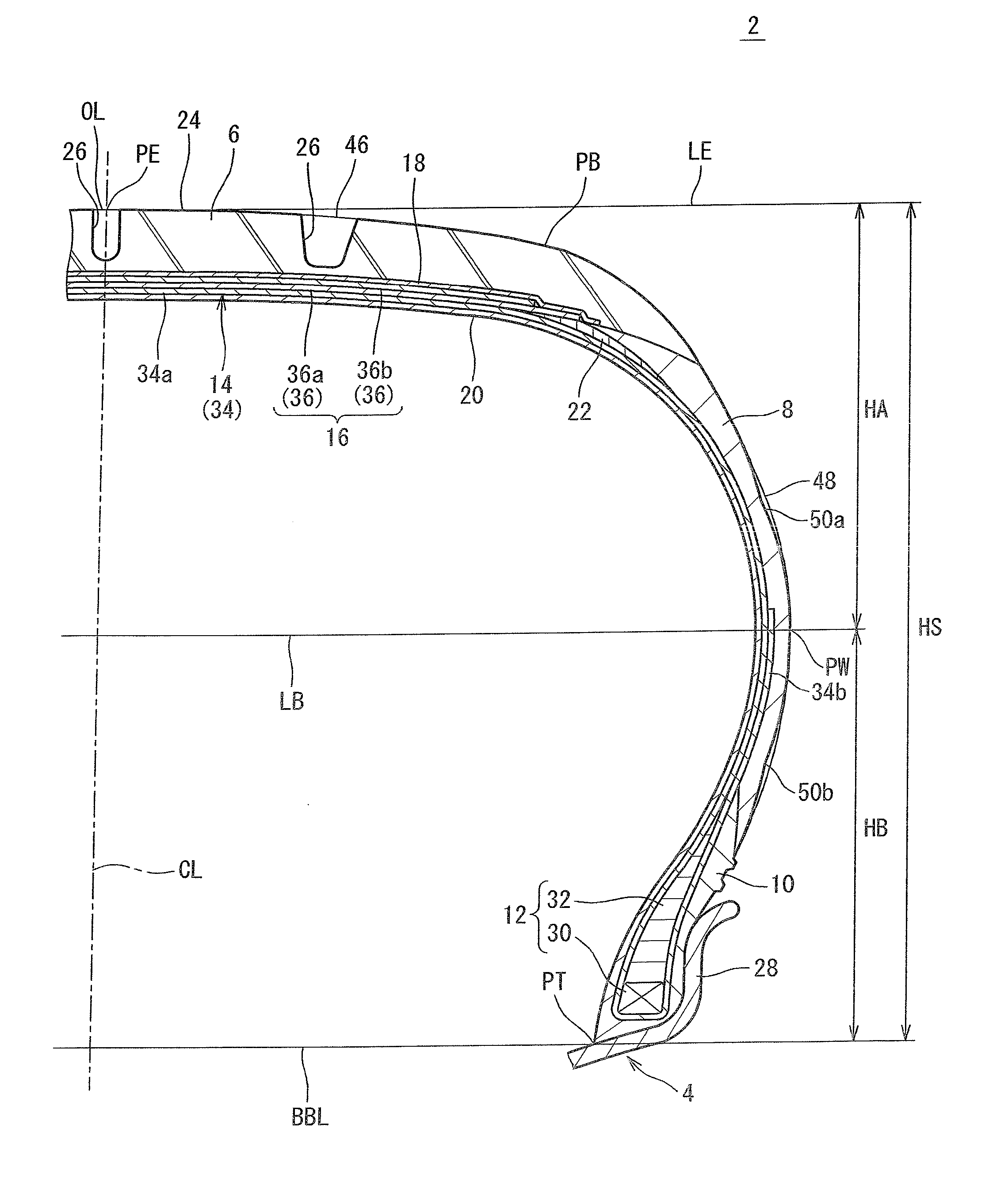
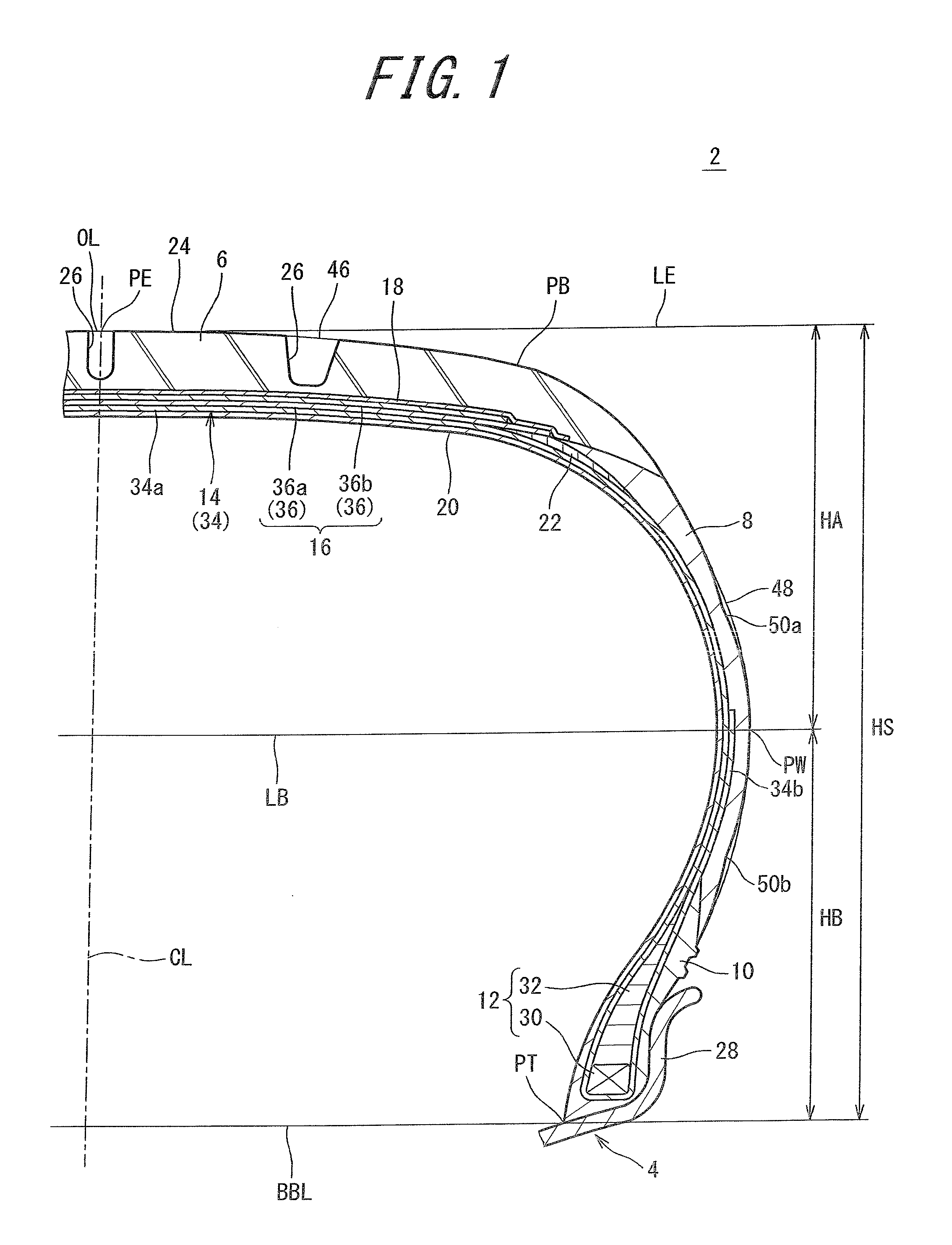
[0053]FIG. 1 illustrates a pneumatic tire 2. In FIG. 1, the up-down direction represents the radial direction of the tire 2, the right-left direction represents the axial direction of the tire 2, and the direction perpendicular to the surface of the sheet represents the circumferential direction of the tire 2. In FIG. 1, an alternate long and short dash line CL represents the equator plane of the tire 2. The tire 2 has a shape which is symmetric about the equator plane except for a tread pattern.

[0054]The tire 2 is mounted to a rim 4. The rim 4 is a normal rim. The tire 2 is inflated with air. An internal pressure of the tire 2 is a normal internal pressure. In the present invention, the dimensions and angles of the components of the tire 2 are measured in a state where the tire 2 is mounted to a normal rim, and inflated with air to a normal internal pressure. During the measurement, no load is applied to the tire 2. In the description herein, the normal rim represents a rim that is...

second embodiment

[0127]FIG. 6 shows a pneumatic tire 102 to which a method for determining a carcass profile according to one embodiment of the present invention can be applied. In FIG. 6, the up-down direction represents the tire radial direction (hereinafter, also referred to simply as the radial direction), the right-left direction represents the tire axial direction (hereinafter, also referred to simply as the axial direction), and the direction perpendicular to the surface of the sheet represents the tire circumferential direction (hereinafter, also referred to simply as the circumferential direction). In FIG. 6, an alternate long and short dash line CL represents the center line of the meridian cross-section of the tire 102, and also represents the equator plane. The tire 102 has a shape which is symmetric about the equator plane except for a tread pattern. An alternate long and two short dashes line BL represents a bead base line of the tire 102. The tire 102 includes a tread 104, sidewalls 1...

examples

[0181]Hereinafter, effects of the present invention will become apparent according to examples. However, the present invention should not be restrictively construed based on the description of examples.


PUM


Abstract

[Object] A pneumatic tire 2 that allows achievement of reduction of rolling resistance without taking influence on a mass into consideration, is provided.
[Solution] A profile OL of the tire 2 includes a ground-contact surface 46 and a pair of side surfaces 48. In the profile OL, a zone from a point PB to a point PW is formed by three arcs. The arcs are a first arc, a second arc that extends almost outward from the first arc in the radial direction, and a third arc that extends almost outward from the second arc further in the radial direction. A ratio of a radius R2 of curvature of the second arc to a radius R1 of curvature of the first arc is greater than or equal to 1.45 and not greater than 3.26. A ratio of a radius R3 of curvature of the third arc to the radius R1 of curvature of the first arc is greater than or equal to 0.45 and not greater than 0.56. Each sidewall 8 of the tire 2 has a first recess 50a and a second recess 50b that are recessed inward from the side surface 48.

Description

TECHNICAL FIELD[0001]The present invention relates to pneumatic tires.BACKGROUND ART[0002]In recent years, development of vehicles that allow fuel consumption to be reduced in consideration of the environment is advanced. Pneumatic tires are mounted to the vehicles. The pneumatic tires act to support vehicle bodies, and to transmit power with respect to road surfaces. The tires exert influence on fuel efficiency of the vehicles.[0003]Development of tires is also advanced in view of achieving reduction in fuel consumption of vehicles. In this development, examination is made so as to focus on rolling resistance of the tires. An exemplary examination is disclosed in JP2005-219537.[0004]Conventionally, for commercially available replacement tires, multiple sizes of the tires are lined up for one tread pattern. Up to more than 70 sizes of tires are lined up for one tread pattern in some cases. The tire sizes are defined in the standard (for example, JATMA standard). The tire size is rep...

Claims


Application Information

Patent Timeline
Patent Type & Authority Applications(United States)
IPC IPC(8): B60C3/04B60C13/00B60C15/06B60C9/18B60C15/00B60C11/00B60C9/02
CPCB60C3/04B60C11/00B60C13/00B60C9/02B60C9/18B60C15/00B60C15/06B60C15/0036B60C13/003B60C13/02B60C9/0292Y02T10/86
Inventor TOMITA, SHINTAROTANAKA, SUSUMUASANO, KAZUO
Owner SUMITOMO RUBBER IND LTD
Why Eureka
Try Eureka