Lens array optical system
an array optical system and array optical technology, applied in the field of lenses array optical systems, can solve the problem of narrow depth of focus of imaging beams
- Summary
- Abstract
- Description
- Claims
- Application Information
AI Technical Summary
Benefits of technology
Problems solved by technology
Method used
Image
Examples
example 1
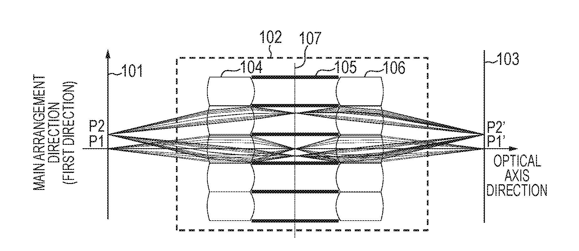
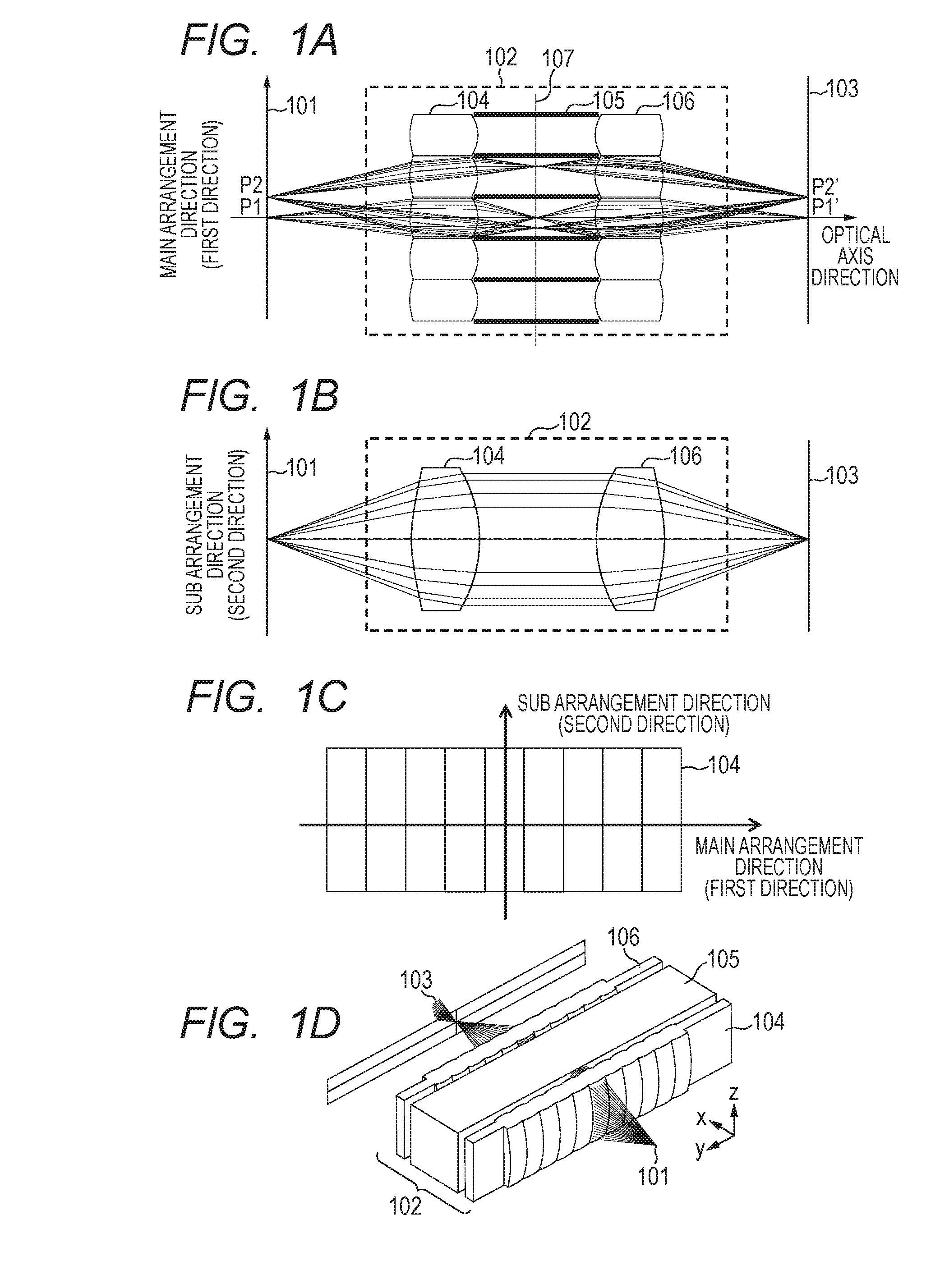
[0046]A first embodiment of the present invention is an example in which a lens array optical system of the present invention is applied to an image forming apparatus. The lens array optical system is constructed inside an exposure unit of the image forming apparatus. FIG. 1A to FIG. 1D are illustrations of a configuration of the exposure unit.
[0047]FIG. 1A is a cross-sectional view of the exposure unit in a plane including a main arrangement direction and an optical axis direction. FIG. 1B is a cross-sectional view of the exposure unit in a plane perpendicular to the main arrangement direction. FIG. 1C is a front view of the exposure unit when viewed from a light source. FIG. 1D is a perspective view of the exposure unit. Note that, in the drawings, only a part of the lens array optical system is illustrated for the sake of convenience, which, however, does not affect the description of the lens array optical system.
[0048]When lens surfaces of a lens optical system are spherical su...
example 2
[0093]A second embodiment of the present invention is an example in which a lens array optical system of the present invention is applied to an image forming apparatus. The lens array optical system in the second embodiment is constructed inside an exposure unit of the image forming apparatus.
[0094]FIG. 5A to FIG. 5D are illustrations of a configuration of the exposure unit in the second embodiment. FIG. 5A is a cross-sectional view of the exposure unit in a plane including a main arrangement direction and an optical axis direction. FIG. 5B is a cross-sectional view of the exposure unit in a plane perpendicular to the main arrangement direction. FIG. 5C is a front view of the exposure unit when viewed from a light source. FIG. 5D is a perspective view of the exposure unit. Note that, in the drawings, only a part of the lens array optical system is illustrated for the sake of convenience, which, however, does not affect the description of the lens array optical system.
[0095]Now, the ...
example 3
[0130]A third embodiment of the present invention is an example in which a lens array optical system of the present invention is applied to an image forming apparatus. The lens array optical system in the third embodiment is constructed inside an exposure unit of the image forming apparatus.
[0131]FIG. 8A to FIG. 8D are illustrations of a configuration of the exposure unit in the third embodiment. FIG. 8A is a cross-sectional view of the exposure unit in a plane including a main arrangement direction and an optical axis direction. FIG. 8B is a cross-sectional view of the exposure unit in a plane perpendicular to the main arrangement direction. FIG. 8C is a front view of the exposure unit when viewed from a light source. FIG. 8D is a perspective view of the exposure unit. Note that, in the drawings, only a part of the lens array optical system is illustrated for the sake of convenience, which, however, does not affect the description of the lens array optical system.
[0132]Now, the dif...
PUM
 Abstract
Description
Claims
Application Information
 - R&D
- Intellectual Property
- Life Sciences
- Materials
- Tech Scout
- Unparalleled Data Quality
- Higher Quality Content
- 60% Fewer Hallucinations
Browse by: Latest US Patents, China's latest patents, Technical Efficacy Thesaurus, Application Domain, Technology Topic, Popular Technical Reports.
© 2025 PatSnap. All rights reserved.Legal|Privacy policy|Modern Slavery Act Transparency Statement|Sitemap|About US| Contact US: help@patsnap.com


