
Liquid crystal display device having at least three electrodes in each pixel area

Inactive Publication Date: 2016-07-14
VASTVIEW TECH
View PDF7 Cites 3 Cited by
  • Summary
  • Abstract
  • Description
  • Claims
  • Application Information

AI Technical Summary

Benefits of technology

The present invention is an LCD device that offers a wide viewing angle and low flicker without requiring complicated manufacturing processes. It consists of a first substrate, a first alignment layer, a liquid crystal layer, a second alignment layer, a passivation layer, and a second substrate. The device also has multiple pixel areas.

Problems solved by technology

However, because the LC molecules are aligned in a vertical alignment manner, when the LC molecules are applied with a low voltage and the LCD device is watched at an inclined viewing angle, a gray-level inversion problem occurs, which causes the problem of color shift at an inclined viewing angle and influences a normal presentation of images of the LCD device.
However, the methods for solving the above mentioned problem in the prior arts have complicated LCD device processes.

Method used


Image

  • Liquid crystal display device having at least three electrodes in each pixel area
  • Liquid crystal display device having at least three electrodes in each pixel area
  • Liquid crystal display device having at least three electrodes in each pixel area

Examples


first embodiment

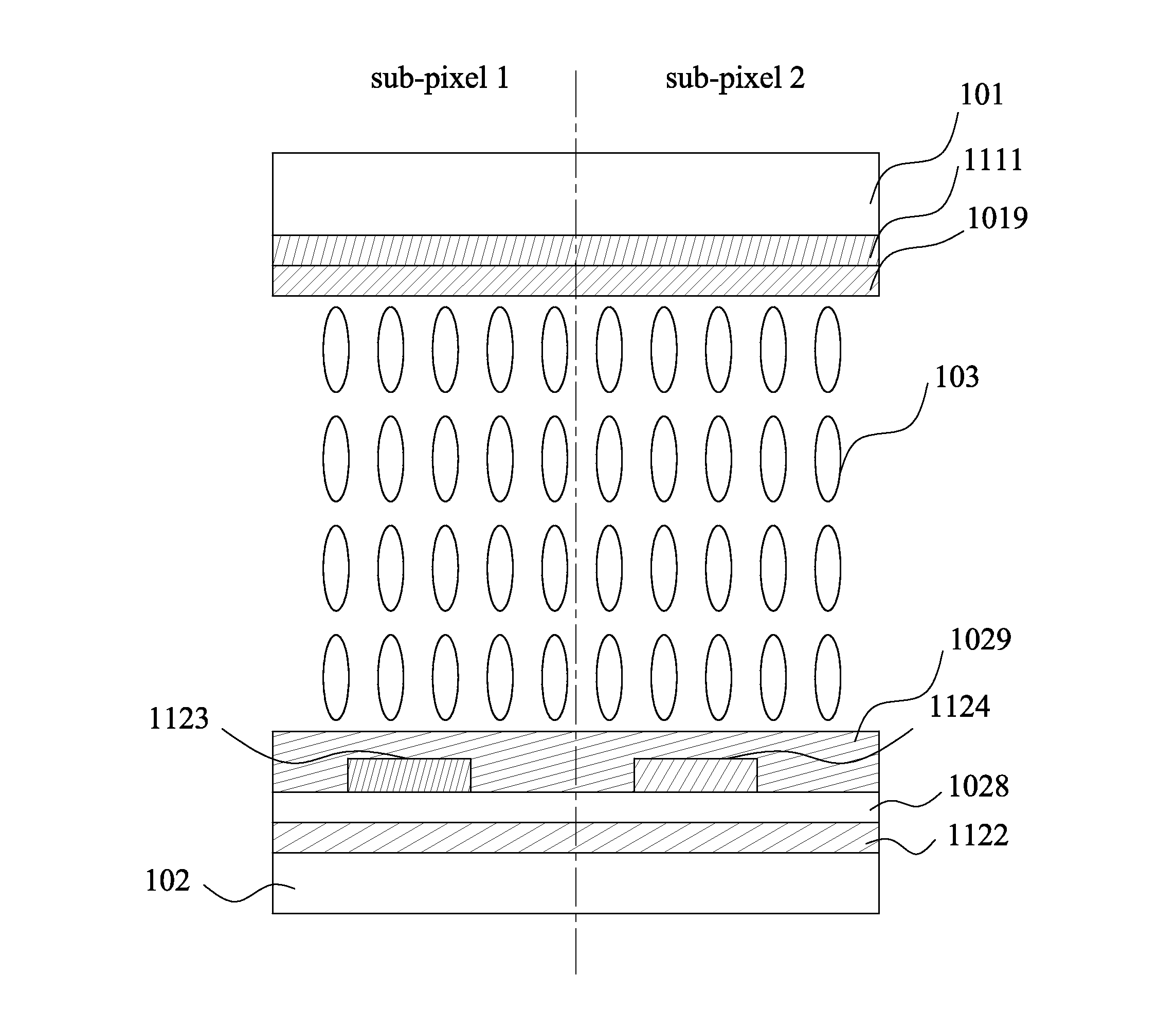
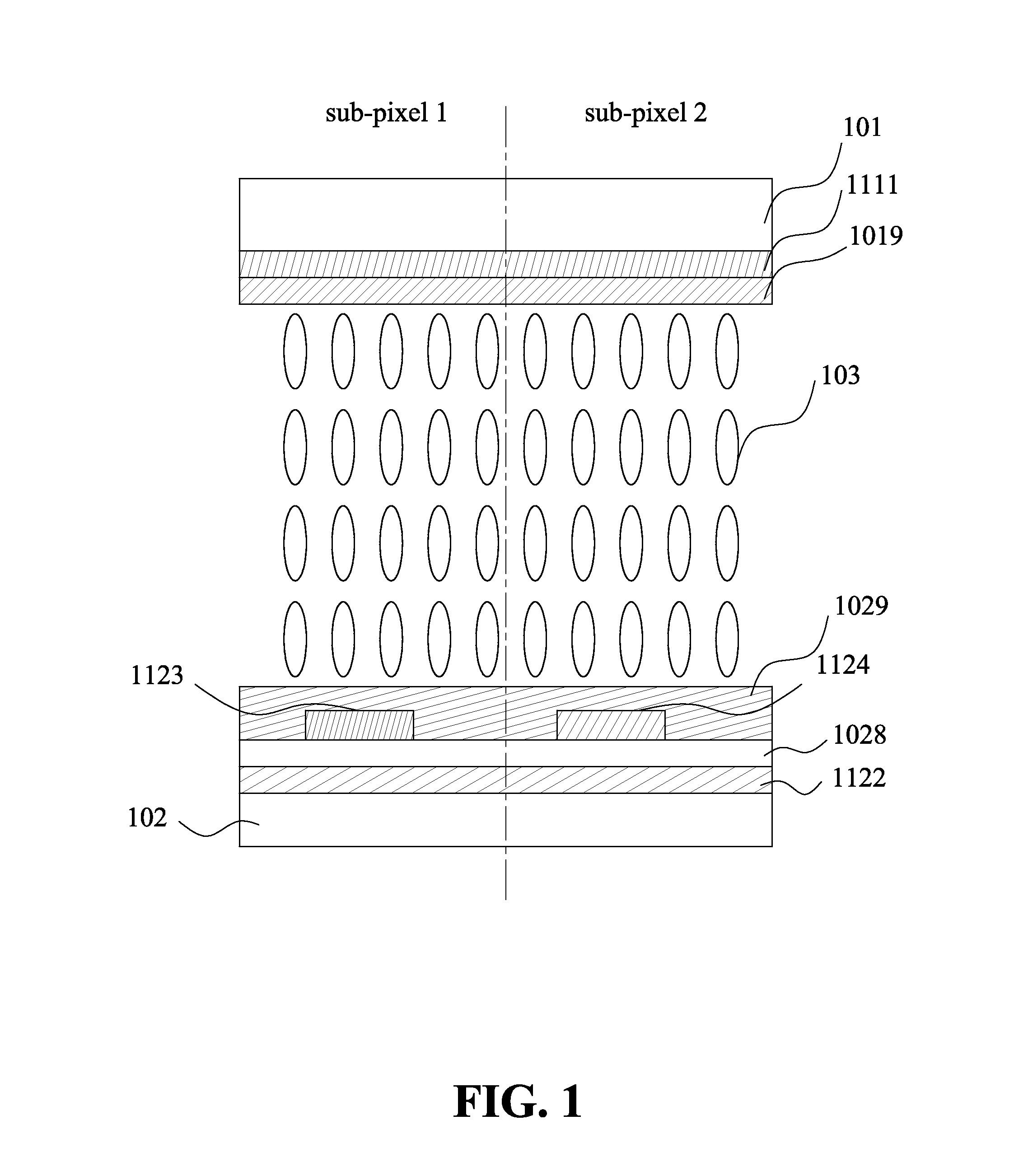
[0042]FIG. 1 shows a cross sectional view of an LCD device having at least three electrodes according to the present invention. With reference to FIG. 1, the LCD device of the present invention comprises a first substrate 101, a second substrate 102 and a liquid crystal layer 103 disposed between the first and second substrates.

[0043]A plurality of pixel areas is formed on the LCD device. Each pixel area includes a first electrode 1111 formed on the first substrate 101 and a second electrode 1122 formed on the second substrate 102. The first electrode 1111 is the common electrode of the pixel area. Both first electrode 1111 and second electrode 1122 are non-patterned planar electrodes covering the pixel area. The pixel area is divided into at least two sub-pixel areas.

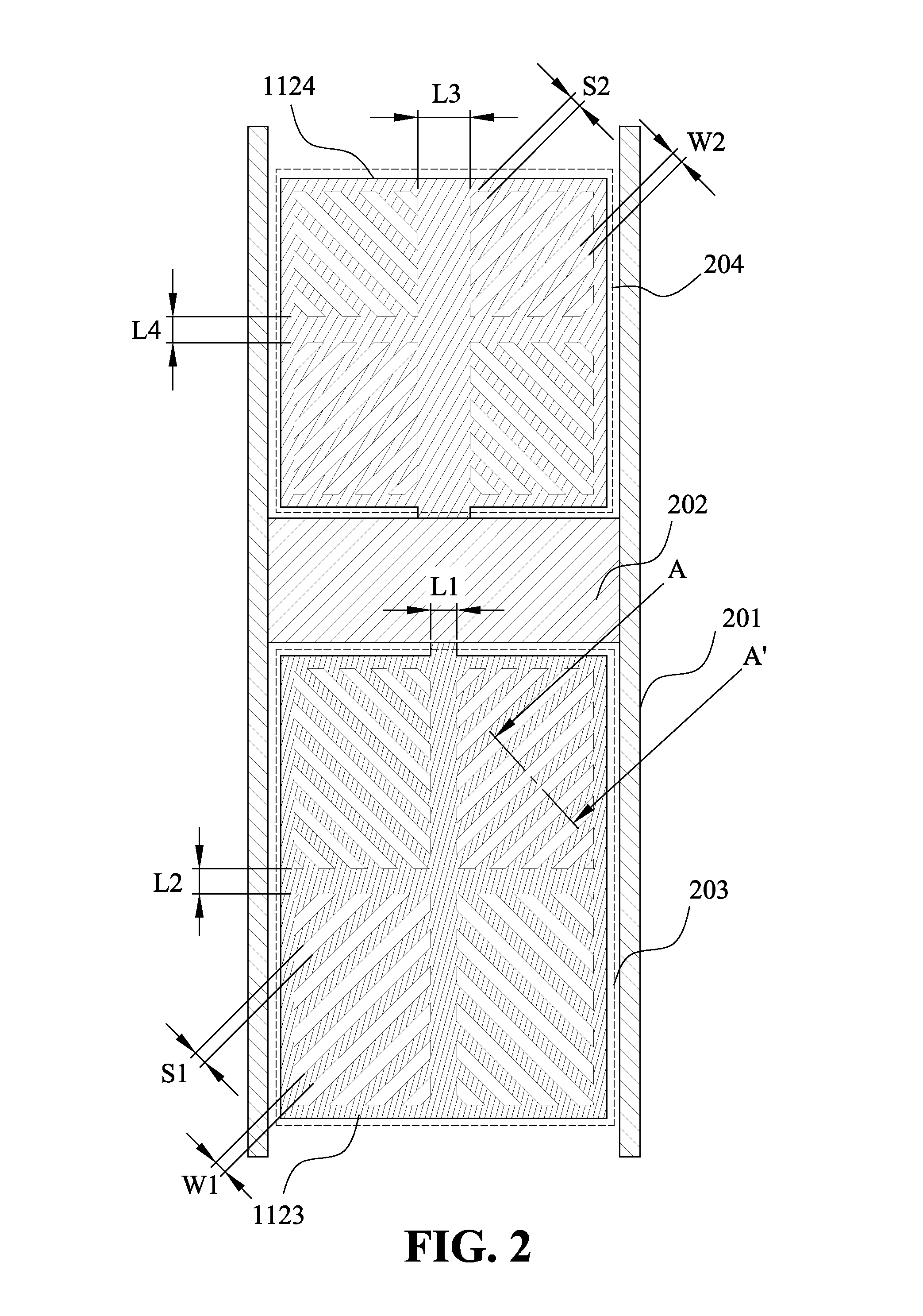
[0044]A passivation layer 1028 is formed above the second electrode 1122, and a third electrode 1123 and a fourth electrode 1124 are respectively formed in the two sub-pixel areas on the passivation layer 1028 as shown...

second embodiment

[0076]In the second embodiment shown in FIG. 17, the LCD structure is almost identical to that of FIG. 1 except that the non-patterned first electrode 1111 formed on the first substrate 101 in FIG. 1 is replaced by two separate non-patterned planar electrodes 1311 and 1315 respectively in the first and second sub-pixel areas.

[0077]As can be seen from FIG. 17, the two electrodes 1311 and 1315 are applied with Vcom and V5 respectively. The second electrode 1122 is applied with an AC voltage VP. The third and fourth electrodes are applied with AC voltage Vb1 and Vb2 respectively. V5 is a DC voltage equal to or different from Vcom. V5 may also be an AC voltage identical to Vb1 or Vb2.

[0078]FIG. 18 shows a cross sectional view of an LCD device having at least three electrodes according to a variation of the second embodiment of the present invention. As can be seen from FIG. 18, the LCD structure is very similar to that shown in FIG. 17 except that in each sub-pixel area of this embodime...


PUM


Abstract

A liquid crystal display (LCD) device includes at least three electrodes disposed between a liquid crystal layer and two substrates in each pixel area with at least one electrode between the liquid crystal layer and each of the two substrates. Each pixel area has at least two sub-pixel areas applied with different electrode voltages. One of the electrodes is applied with a DC voltage. Two of the electrodes are applied respectively with first and second AC voltages synchronous with an LCD timing signal. Both first and second AC voltages have a high-level period and a low-level period equal to the high-level period. The timing period of the LCD timing signal is at least one or more times of the high-level periods of the two AC voltages with the high-level period of the first AC voltage longer than the high-level period of the second AC voltage.

Description

BACKGROUND OF THE INVENTION[0001]1. Field of the Invention[0002]The present invention relates to a liquid crystal display (LCD) device, and more particularly to an LCD device having sub-pixel areas in each pixel for improving viewing angle and reducing flicker.[0003]2. Description of Related Arts[0004]An LCD device controls the light transmittance by using the characteristic that liquid crystal (LC) molecules present different light polarization or refraction effects under different alignments so as to produce images. A twisted nematic (TN) LCD device has good light transmittance but an extremely narrow viewing angle as influenced by the structure and optical characteristic of the LC molecules.[0005]To solve the transmittance and viewing angle problems, a twisted vertical alignment model has been proposed so as to provide the high transmittance and the wide viewing angle. However, because the LC molecules are aligned in a vertical alignment manner, when the LC molecules are applied ...

Claims


Application Information

Patent Timeline
IPC IPC(8): G09G5/18G09G3/36
CPCG09G5/18G09G2300/0426G09G3/3696G09G3/3607G09G3/3614G09G2320/028G02F1/134309G09G2300/0443G09G2310/08
Inventor PENG, CHENG CHUNGSHEN, YUHREN
Owner VASTVIEW TECH
Features
  • Generate Ideas
  • Intellectual Property
  • Life Sciences
  • Materials
  • Tech Scout
  • Unparalleled Data Quality
  • Higher Quality Content
  • 60% Fewer Hallucinations
Learn More