Electrical connector

a technology of electrical connectors and connectors, applied in the field of cables, can solve the problems of wasting time, unsteadiness or distortion of signals, and difficulty in wiring electrical connectors to cables

Inactive Publication Date: 2016-07-14
CHANT SINCERE
View PDF13 Cites 16 Cited by
  • Summary
  • Abstract
  • Description
  • Claims
  • Application Information

AI Technical Summary

Benefits of technology

[0005]A cable and an electronic device transmit signals via a connector assembly. The connector assembly includes an electrical connector and a socket connector compatible with the electrical connector. The electrical connector includes a metal casing, a plastic core body, terminals, and so on. For a conventional electrical connector, the transmission line of the cable need to be inserted into the electrical connector so as to be welded to connect to the terminals in the electrical connector, which leads to difficulty in wiring the electrical connector to the cable and the waste of time.

Problems solved by technology

For a conventional electrical connector, the transmission line of the cable need to be inserted into the electrical connector so as to be welded to connect to the terminals in the electrical connector, which leads to difficulty in wiring the electrical connector to the cable and the waste of time.
The coupling phenomena between terminals include capacitive coupling or inductive coupling, wherein capacitive coupling causes coupling current and inductive coupling causes coupling voltage, and both coupling current and coupling voltage result in unsteadiness or distortion of the signals.

Method used


Image

  • Electrical connector
  • Electrical connector
  • Electrical connector

Examples


Embodiment Construction

)

[0028]The preferred embodiments of the present invention are described in detail below with reference to FIG. 1 to FIG. 11. The description is used for explaining the embodiments of the present invention only, but not for limiting the scope of the claims.

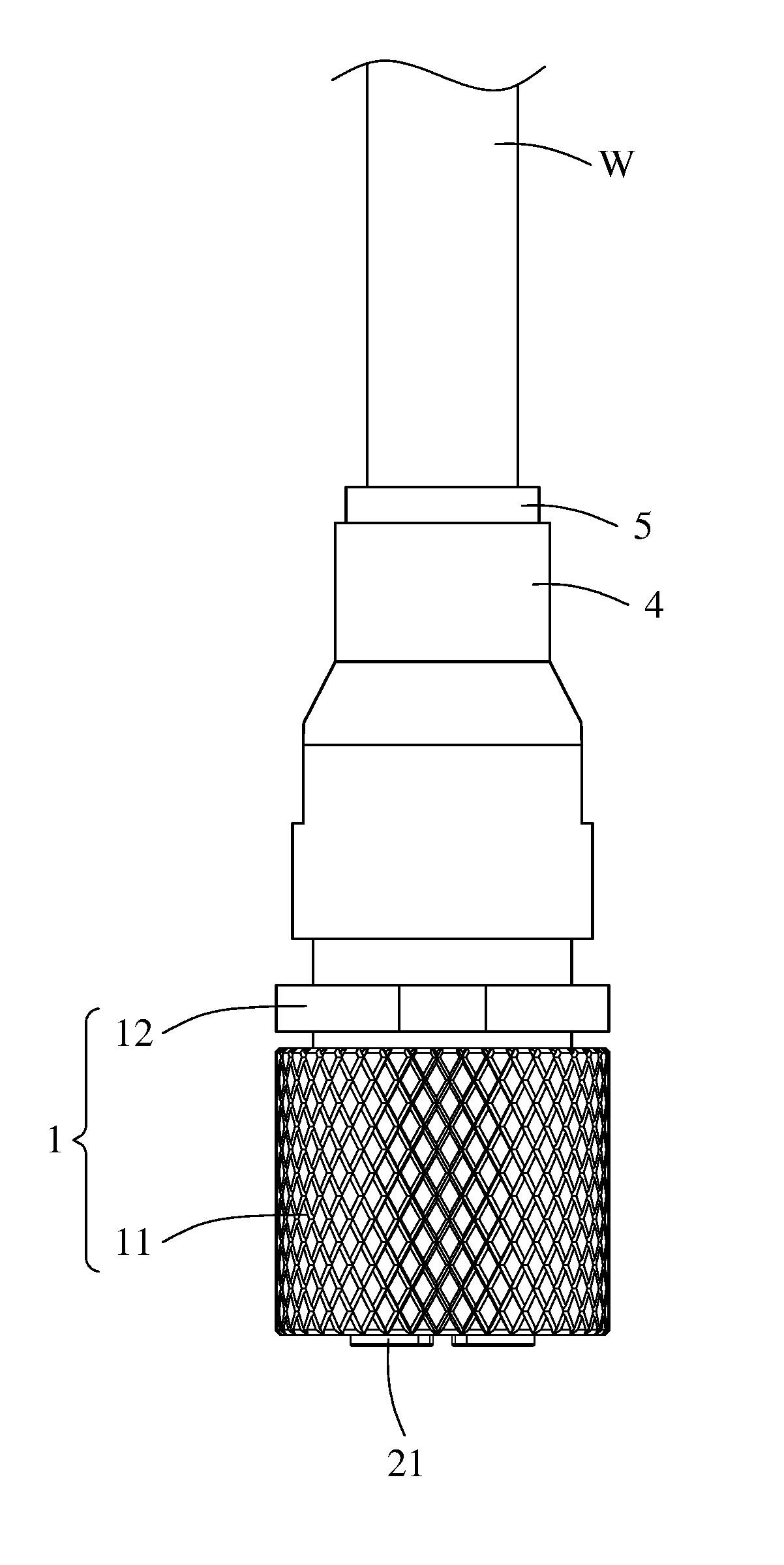
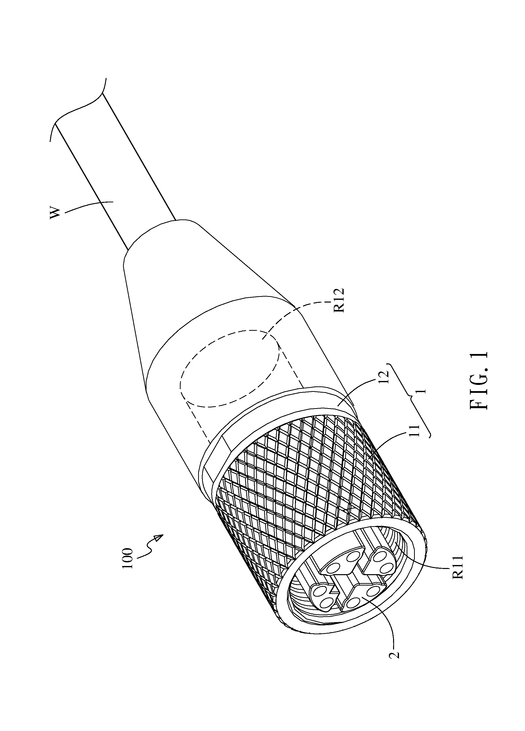
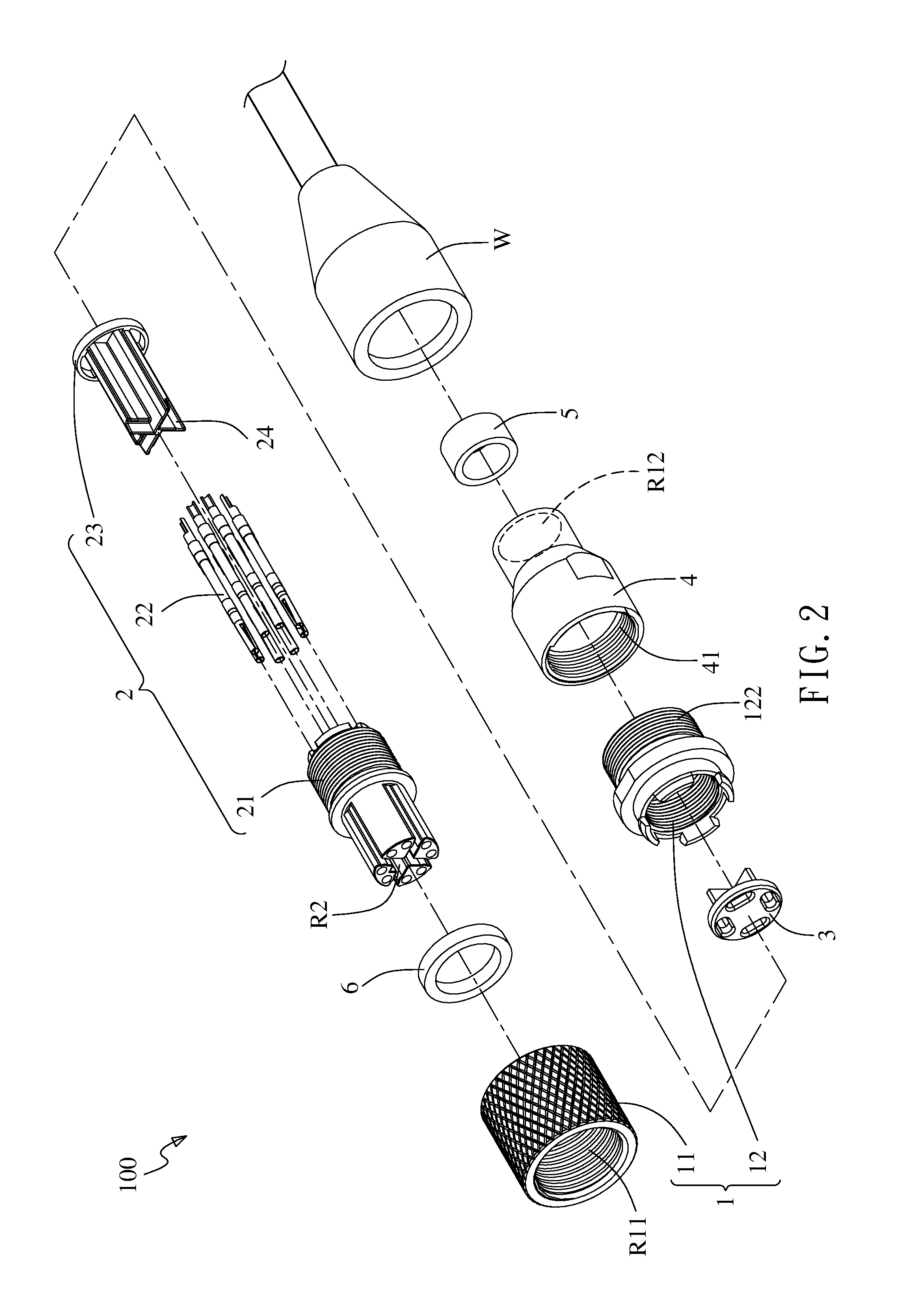
[0029]As shown in FIG. 1 to FIG. 4, an electrical connector 100 of a cable W according to an embodiment of the present invention comprises: a connecting casing 1, a terminal assembly 2, and a receiving member 3.

[0030]The connecting casing 1 includes a covering shell portion 11 and a connecting portion 12, wherein the covering shell portion 11 and the connecting portion 12 are sleeved to each other in a front-rear direction and form an internal space (not shown) penetrating the connecting casing 1 in the front-rear direction. The covering shell portion 11 includes a front-side socket R11 and a rear-side socket R12, in which the front-side socket R11 is provided to connect a compatible electrical connector 100, and the rear-side sock...


PUM


Abstract

An electrical connector includes a connecting casing, a terminal assembly and a receiving member, in favor to attaching on a cable. Each rear end of a plurality of terminals of the terminal assembly protrude to a terminal carrier of the terminal assembly in furtherance to penetrate through the receiving member up till the terminals being exposed out of a rear-side socket of the connecting casing.

Description

CROSS-REFERENCE TO RELATED APPLICATIONS[0001]This application claims the benefit of the filing date under 35 U.S.C. §119(a)-(d) of Taiwan Patent Applications No. 104200375, filed Jan. 12, 2015.BACKGROUND OF THE INVENTION[0002]1. Field of the Invention[0003]The present invention relates to a cable, and more particularly to an electrical connector assembled on a cable.[0004]2. Description of the Related Art[0005]A cable and an electronic device transmit signals via a connector assembly. The connector assembly includes an electrical connector and a socket connector compatible with the electrical connector. The electrical connector includes a metal casing, a plastic core body, terminals, and so on. For a conventional electrical connector, the transmission line of the cable need to be inserted into the electrical connector so as to be welded to connect to the terminals in the electrical connector, which leads to difficulty in wiring the electrical connector to the cable and the waste of ...

Claims


Application Information

Patent Timeline
Patent Type & Authority Applications(United States)
IPC IPC(8): H01R24/38H01R13/52
CPCH01R24/38H01R2101/00H01R13/5202H01R13/6463
Inventor LIN, YONG-SHENGCHIEN, YU CHINFAN, CHENG-HUI
Owner CHANT SINCERE
Why Eureka
Try Eureka