Clamping assembly

a technology of assembly and clamping rod, which is applied in the direction of snap fasteners, buckles, manufacturing tools, etc., can solve the problems of lowering efficiency and complex operation

Inactive Publication Date: 2013-08-08
SHENZHENSHI YUZHAN PRECISION TECH CO LTD +1
View PDF27 Cites 3 Cited by
  • Summary
  • Abstract
  • Description
  • Claims
  • Application Information

AI Technical Summary

Problems solved by technology

However, during the clamping of the clamping assembly, the screw must be adjusted to allow the clamping blocks to provide a suitable distance for the workpiece, which results in a complex operation.
In addition, when the clamping assembly needs to clamp or release workpieces frequently, it is a waste of time and leads to having lowered efficiency.

Method used


Image

  • Clamping assembly
  • Clamping assembly
  • Clamping assembly

Examples


Embodiment Construction

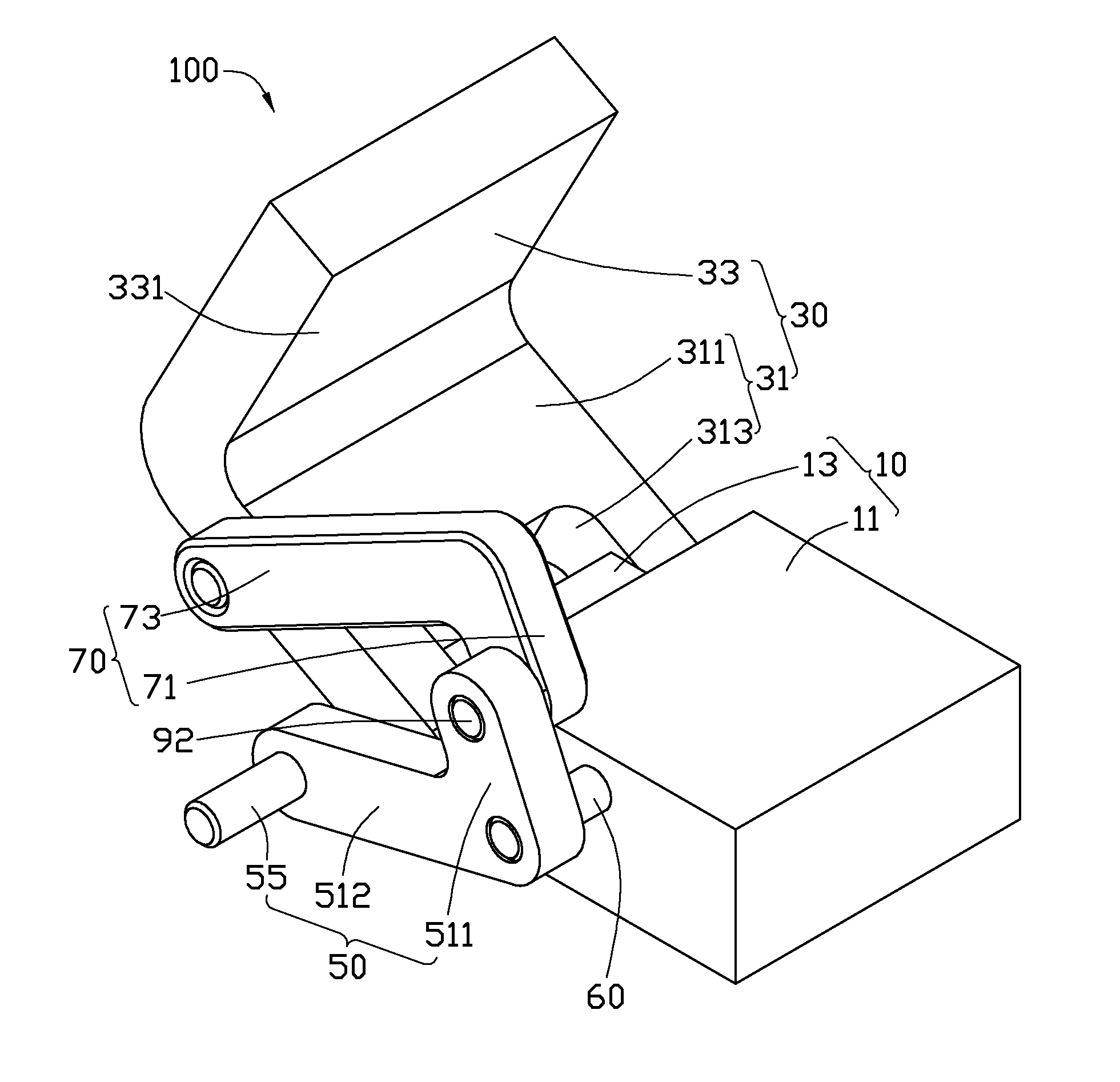
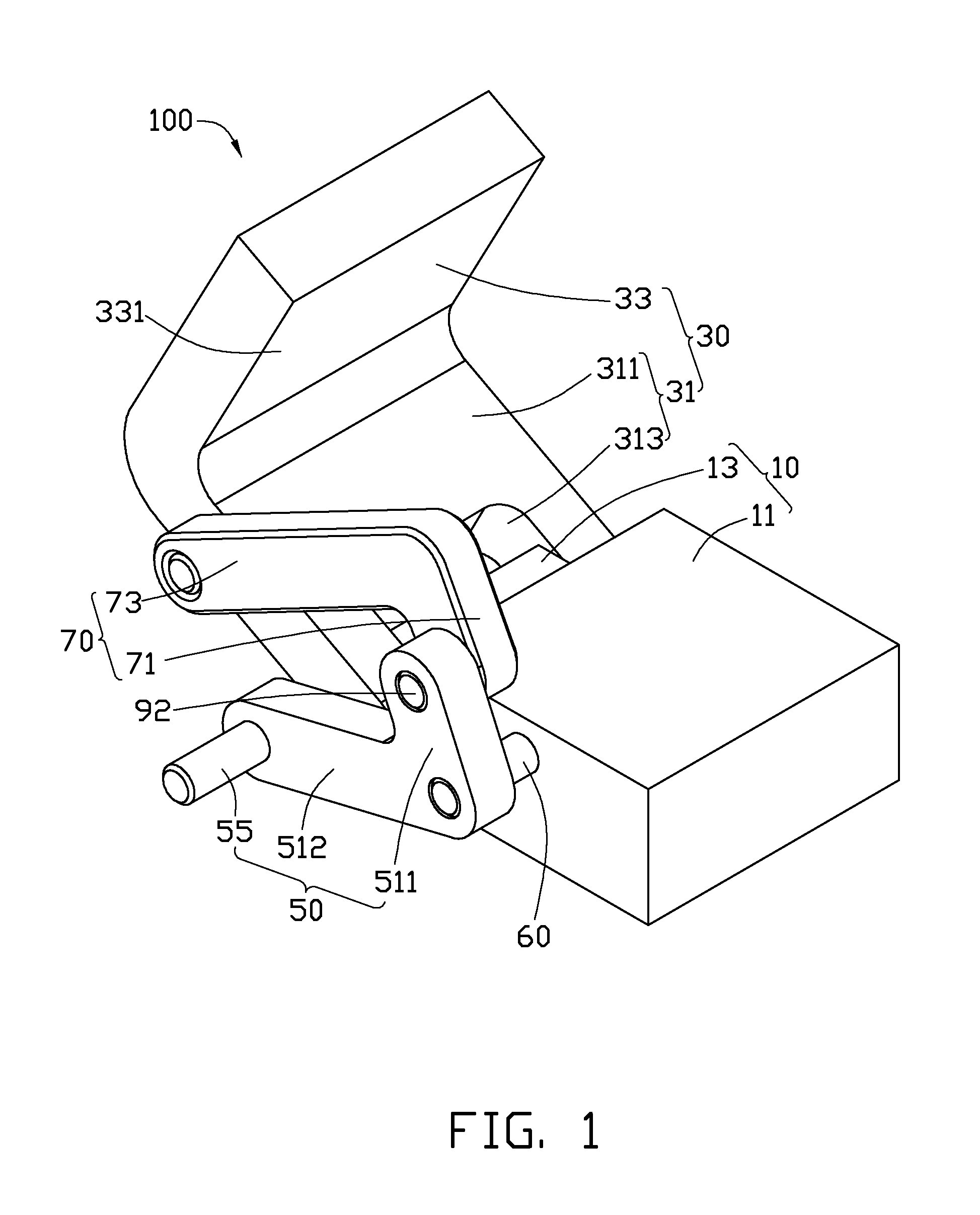
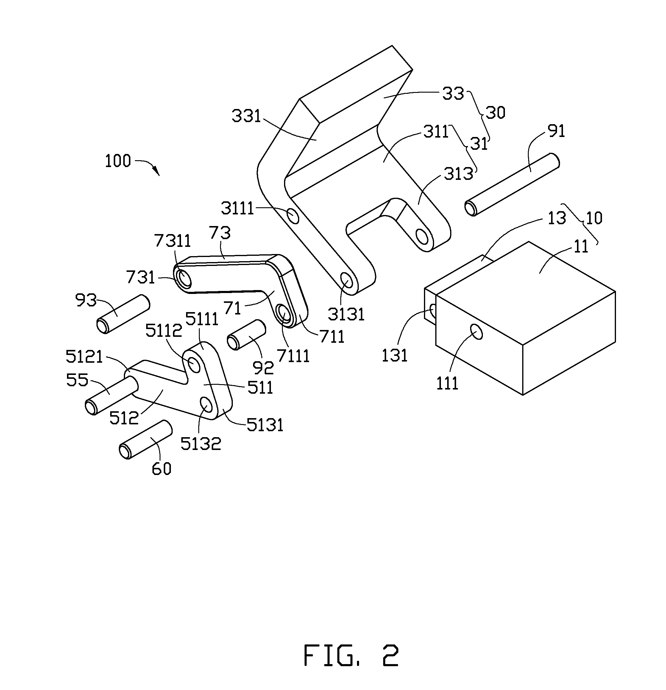
[0011]FIGS. 1 through 3 show a clamping assembly 100, for clamping a workpiece 200. The clamping assembly 100 includes a base 10, a clamping block 30, a first linkage 50, a shaft rod 60, a second linkage 70, a first pivot member 91, a second pivot member 92, and a third pivot member 93. The clamping block 30 is rotatably connected to the base 10 via the first pivot member 91. The first linkage 50, the shaft rod 60, the second linkage 70, the second pivot member 92, and the third pivot member 93 are located at a same side of the base 10 and the clamping block 30. In the illustrated embodiment, the first pivot member 91, the second pivot member 92, and the third pivot member 93 are pins.

[0012]The base 10 is substantially cubic, and includes a main body 11 and a mounting portion 13 outwardly extending from an end of the main body 11. The main body 11 is substantially cubic, and defines an inserting hole 111 at a side surface thereof. The mounting portion 13 is substantially cubic, and ...


PUM


Abstract

A clamping assembly includes a base, a clamping block, a first linkage, and a second linkage. The clamping block includes a rotating portion and a clamping portion. The rotating portion is rotatably connected to the base. The clamping portion extends out from the rotating portion towards the base. The first linkage is rotatably connected to the base, and includes a first rod portion and a second rod portion extending from the first rod portion. The second linkage includes a third rod portion and a fourth rod portion extending from the third rod portion. The third rod portion rotatably connects with the first rod portion. The fourth rod portion rotatably connects with the rotating portion of the clamping block.

Description

BACKGROUND[0001]1. Technical Field[0002]The present disclosure relates to clamping assemblies, particularly to a clamping assembly configured with linkages, for clamping workpieces.[0003]2. Description of Related Art[0004]A clamping assembly clamps workpieces, for assembling, processing, or transmitting the workpieces. The clamping assembly may include a pair of clamping blocks connected by an adjustable screw, which enables the distance between the pair of clamping blocks to be adjusted. Therefore, a workpiece may be clamped between the clamping blocks. However, during the clamping of the clamping assembly, the screw must be adjusted to allow the clamping blocks to provide a suitable distance for the workpiece, which results in a complex operation. In addition, when the clamping assembly needs to clamp or release workpieces frequently, it is a waste of time and leads to having lowered efficiency.[0005]Therefore, there is room for improvement in the art.BRIEF DESCRIPTION OF THE DRAW...

Claims


Application Information

Patent Timeline
Patent Type & Authority Applications(United States)
IPC IPC(8): F16B2/10
CPCF16B2/10Y10T24/44496B25B5/12
Inventor WEN, QING-SONG
Owner SHENZHENSHI YUZHAN PRECISION TECH CO LTD
Why Eureka
Try Eureka