Goods fastening apparatus with improved structures

a technology of fastening apparatus and good, applied in the mechanical field, can solve the problems of shortened working life, difficult operation and control of disengaging gear rack operation, troublesome operation and waste of time, etc., and achieve the effect of improving working efficiency, simple and compact structure, and being easy to implemen

Active Publication Date: 2008-06-24
ZHEJIANG TOPSUN LOGISTIC CONTROL CO LTD
View PDF6 Cites 4 Cited by
  • Summary
  • Abstract
  • Description
  • Claims
  • Application Information

AI Technical Summary

Benefits of technology

[0007]An object of the present invention is to provide a goods fastening apparatus with improved simple and compact structures that is easy to implement, in which the gear rack could be disengaged quickly after use to effectively improve the working efficiency. With the apparatus of the invention, lots of technical problems existing in prior art are resolved, in which the gear rack could only be disengaged one gear tooth by one gear tooth causing troublesome operation and waste of time.
[0008]Another object of the present invention is to provide a goods fastening apparatus with improved structures which is easy to operate and control and saves time and labor. With the apparatus of the invention, some technical problems existing in prior art are resolved, in which the operation of disengaging the gear rack is difficult to conduct and control.
[0009]Yet another object of the present invention is to provide a goods fastening apparatus with improved structures which could make the disengaging mechanism directly act on the driving claw and the position claw without any influence to other features, thereby causing long working life. With the apparatus of the invention, many technical problems existing in prior art are resolved, in which other features are tended to be damaged with long-term use, thereby causing the working life shortened.

Problems solved by technology

With the apparatus of the invention, lots of technical problems existing in prior art are resolved, in which the gear rack could only be disengaged one gear tooth by one gear tooth causing troublesome operation and waste of time.
With the apparatus of the invention, some technical problems existing in prior art are resolved, in which the operation of disengaging the gear rack is difficult to conduct and control.
With the apparatus of the invention, many technical problems existing in prior art are resolved, in which other features are tended to be damaged with long-term use, thereby causing the working life shortened.

Method used


Image

  • Goods fastening apparatus with improved structures
  • Goods fastening apparatus with improved structures
  • Goods fastening apparatus with improved structures

Examples


first embodiment

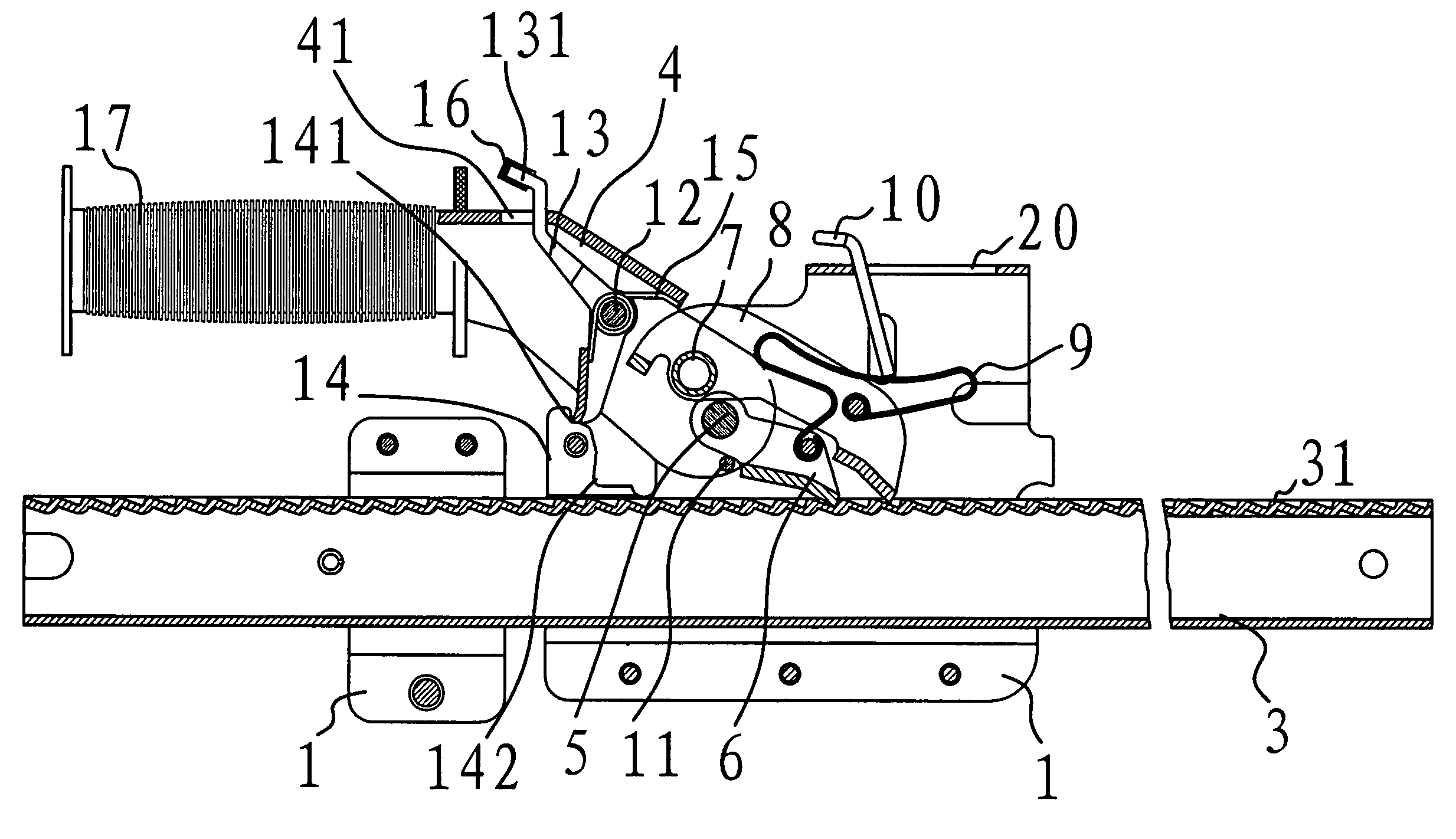
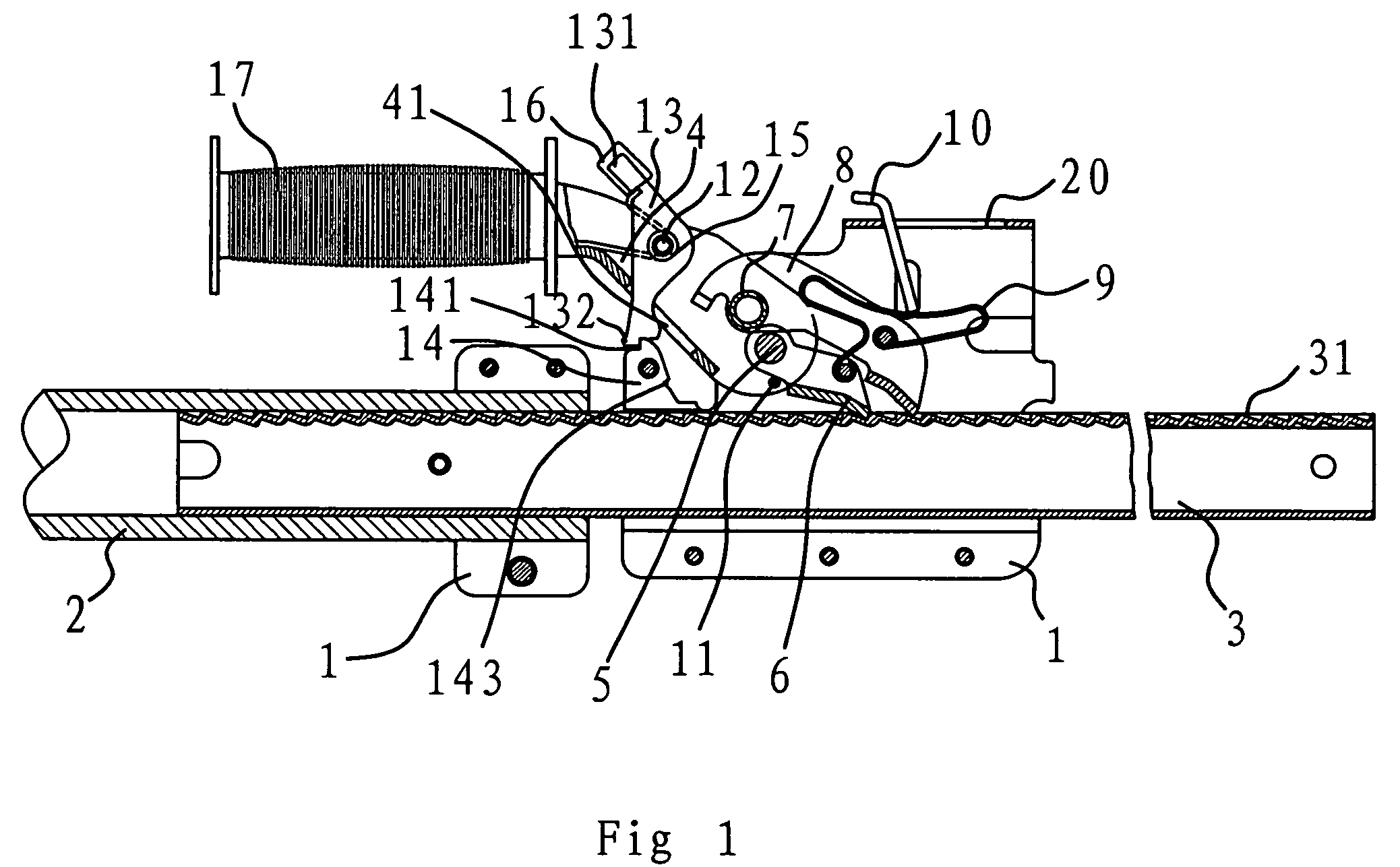
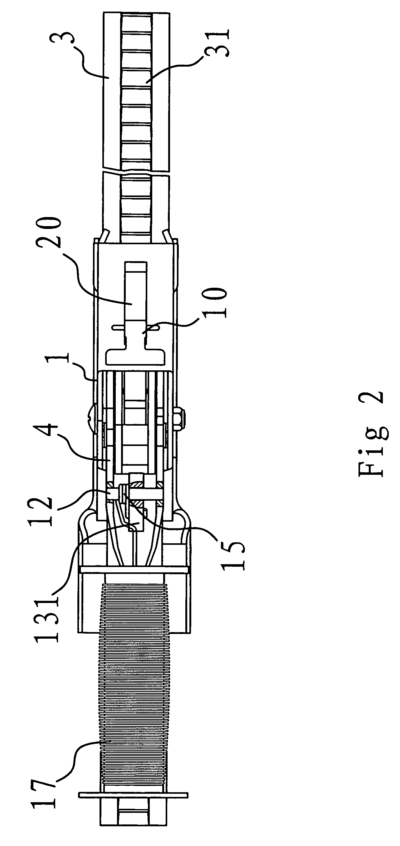
[0049]As shown in FIG. 1 and FIG. 2, a goods fastening apparatus of the invention comprises a body 1, a pipe 2, a gear rack 3, a positioning claw 6 and a driving claw 8. In this embodiment, the gear rack 3 is shaped by firstly pressing a bar plate into tooth form and then molding it by a tuber. The length of the gear rack 3 thus made can vary depending on the actual needs with much flexibility. The gear rack 3 of the present invention has obvious advantages compared to that manufactured by conventional casting methods.

[0050]The pipe 2 is fixedly connected to the body 1. The gear rack 3 passes through the body 1 and is partly muff-coupled with the inside of the pipe 2. A hand grip 4 and the positioning claw 6 are hinged to the body 1 through a primary pivot 5. A driving claw 8 is hinged to the hand grip 4 through a secondary pivot 7. A plate spring 9 is positioned between the driving claw 8 and the positioning claw 6. A grip cover 17 is covered on the hand grip 4. In order to prevent...

second embodiment

[0060]In this embodiment, a bar-shaped hole 41 is disposed at the back of the hand grip 4, as shown in FIGS. 9-18. The upper end of the full back wrench 13 extends out of the bar-shaped hole 41. A slot 19 for locating the end of the torsion spring 15 is provided on the full back wrench 13. Moreover, in order to facilitate mounting the sheath 16, three notches 18 are set on the button 131. The stopper 14 has a stopper mouth 141 set at the inner side thereof, on the side of which an arc-like edge 142 is positioned. The lower side face of the full back wrench 13 has a profile corresponding to that of said arc-like edge 142. The description of other parts of this embodiment is omitted for purpose of conciseness, for they are similar to those in the first embodiment.

[0061]If a force for turning the hand grip 4 back is applied in use, an acting force will be applied to the upper end of the full back wrench 13 by one end of the bar-shaped hole 41. This way, the lower end of the full back w...

third embodiment

[0063]In this embodiment, the control device has a full back wrench 13 hinged to the hand grip 4 through a pivot 12 and a stopper 14 fixed to the body 1, as shown in FIG. 19. The lower end face 13a of the full back wrench 13 is a flat surface, and could be pressed against the upper end face 14a of the stopper 14. The full back wrench 13 contacts with one end of the bar-shaped hole 41 with action of the torsion spring 15. In such a case, as shown in FIG. 20, the lower end face 13a of the full back wrench 13 contacts with the upper end face 14a of the stopper 14, so that the hand grip could not keep on turning. The description of other parts of this embodiment is omitted for purpose of conciseness, for they are similar to those in the first embodiment.

[0064]Although a lot of terms such as body 1, pipe 2, gear rack 3, gear tooth 31, hand grip 4, bar-shaped hole 41, primary pivot 5, positioning claw 6, secondary pivot 7, driving claw 8, plate spring 9, mobile stopper sheet 10, stopper p...


PUM


Abstract

A goods fastening apparatus is disclosed which comprises a pipe fixedly connected to a body and a gear rack passing through the body and partly muff-coupled with the inside of the pipe. A hand grip and a positioning claw are hinged to the body through a primary pivot. A driving claw is hinged to the hand grip through a secondary pivot. A plate spring is positioned between the driving claw and the positioning claw. A mobile stopper sheet pressed against the plate spring is provided at the upper portion of the body. A stopper pin is fixed at the hand grip. The stopper pin is positioned at the edge of one side of the positioning claw facing the gear rack while the front end of the positioning claw is embedded into the gear teeth of the gear rack.

Description

BACKGROUND OF THE INVENTION[0001]1. Field of Invention[0002]The present invention relates to mechanical technical field, and more particularly, to a goods fastening apparatus for fixing goods in a boxcar or container.[0003]2. Related Art[0004]The goods on automotive vehicles should be fixed during transportation to prevent dislodging. Cords can be directly used to bind the goods for common open cars. However, ordinary cords can not be used for boxcars or containers. Therefore, in order to achieve the goal of fixing goods, it is necessary to employ special fixing device, such as goods fastening apparatus.[0005]The conventional goods fastening apparatus includes a body, a gear rack, a pipe, a driving claw and a positioning claw. The driving claw and the positioning claw can move alternately by pressing and pulling the hand grip, so that the gear rack is brought to move forward, and the gear rack and the pipe are drawn out, finally the gear rack and the pipe are pressed against the sid...

Claims


Application Information

Patent Timeline
Patent Type & Authority Patents(United States)
IPC IPC(8): B66F1/04
CPCB60P7/15B66F1/04
Inventor RUAN, BOQIN
Owner ZHEJIANG TOPSUN LOGISTIC CONTROL CO LTD
Why Eureka
Try Eureka