Lift-recliner chair

a technology of lift and recliner, which is applied in the direction of chairs, movable seats, wheelchairs/patient conveyances, etc., can solve the problems of reducing the aesthetics of the item of furniture, adding additional design constraints, and complicating the design and manufacturing process

Active Publication Date: 2016-07-21
DEWERTOKIN TECHNOLOGY GROUP CO LTD
View PDF0 Cites 15 Cited by
  • Summary
  • Abstract
  • Description
  • Claims
  • Application Information

AI Technical Summary

Benefits of technology

[0008]According to one aspect of the present invention, there is provided a power operated lift-recliner chair comprising a base section, movable seat and backrest sections and actuator means for moving the seat and backrest sections. The seat section is pivotally. mounted with respect to the base section and the backrest section is pivotally mounted with respect to the seat section. A guide is associated with one of the base and the seat sections and at least one follower is associated with the other of the base and the seat sections and is movable along the guide. The guide is of arcuate form to guide the seat for relative pivoting movement with respect to the base about a pivot axis located at the centre of curvature of the guide to raise and lower the chair. The base section includes a pair of parallel side panels on respective lateral sides of the chair. The seat section includes a pair of elongate side members, adjacent the side panels, which carry the guide or follower associated with the seat section. The elongate side members provide a simple and effective means of mounting the seat section relative to the base, which allows the side panels of the base to provide a guard around the moving parts of the chair on the lateral sides of the chair, and also a fixed structure for mounting fixed arms / armrests on the side of the chair. In this way the fixed arms / armrests can be provided at a height which best suits the user for ingress and egress from the chair when raised and for comfortable sitting when the chair is lowered.

Problems solved by technology

The telescopic nature of nesting inner and outer frames can however place some restriction on the aesthetics of the item of furniture and add additional design constraints.
This can complicate the design and manufacturing process.

Method used


Image

  • Lift-recliner chair
  • Lift-recliner chair
  • Lift-recliner chair

Examples


Embodiment Construction

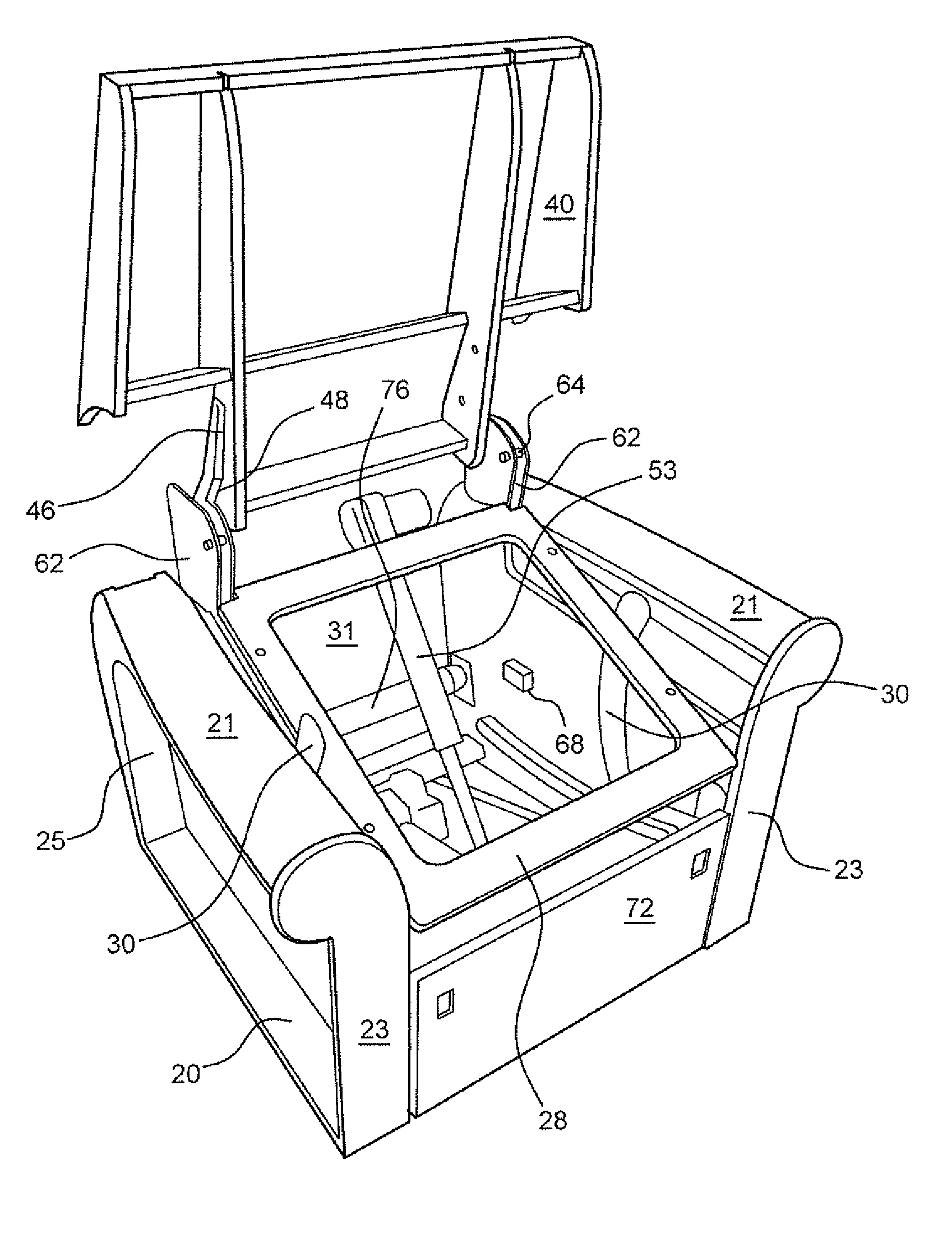
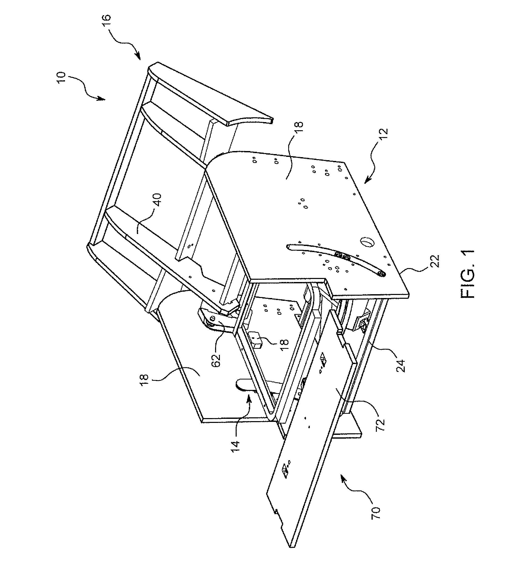
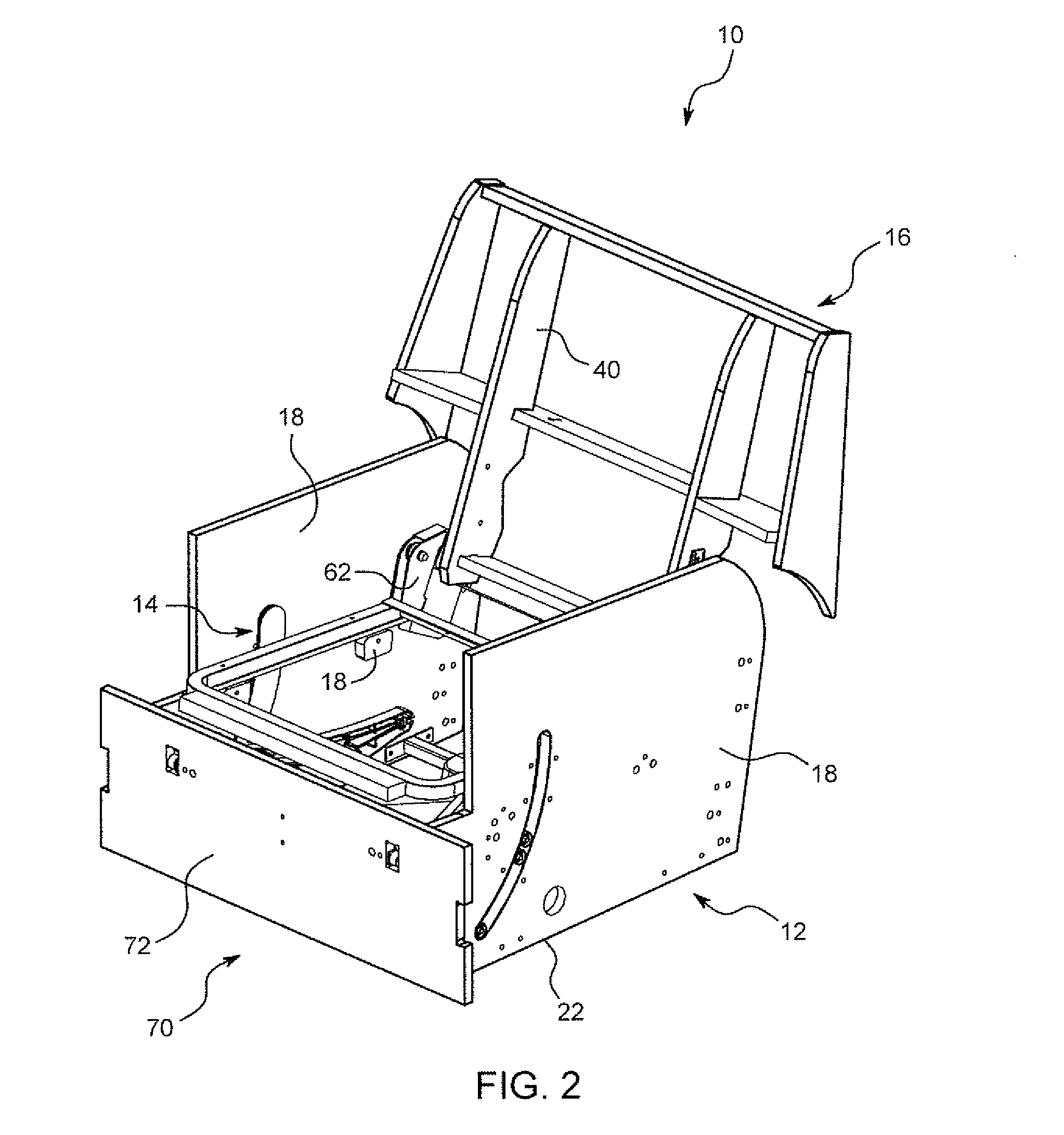
[0062]Reference will now be made in detail to embodiments of the invention. Wherever possible, same or similar reference numerals are used in the drawings and the description to refer to the same or like parts or steps. The drawings are in simplified form and are not to precise scale. The word ‘couple’ and similar terms do not necessarily denote direct and immediate connections, but also include connections through intermediate elements or devices. For purposes of convenience and clarity only, directional (up / down, etc.) or motional (forward / back, etc.) terms may be used with respect to the drawings. These and similar directional terms should not be construed to limit the scope in any manner. it will also be understood that other embodiments may be utilized without departing from the scope of the present invention, and that the detailed description is not to be taken in a limiting sense, and that elements may be differently positioned, or otherwise noted as in the appended claims wi...


PUM


Abstract

A power lift-recliner chair has a base, seat and backrest sections and actuator for moving the seat and backrest sections. The seat is pivotally mounted with respect to the base section and the backrest section is pivotally mounted with respect to the seat section. A guide is associated with one of the base and the seat sections and at least one follower is associated with the other of the base and the seat sections. The guide is arcuate for relative pivoting with respect to the base about a pivot axis located at the centre of curvature of the guide. The base section includes a pair of side panels on lateral sides of the chair. The seat includes a pair of side members, adjacent the side panels, which carry the guide or follower associated with the seat section.

Description

CROSS REFERENCE TO RELATED APPLICATIONS[0001]This application relates to and claims priority as a continuation of Ser. No. PCT / GB2014 / 000385 filed Sep. 29, 2014, the entire contents of which are incorporated herein by reference, which in turn claims priority from GB Ser. No. 1317259.8 filed Sep. 30, 2013.[0002]This application also relates to and claims priority as a continuation-in-part of U.S. Ser. No. 14 / 845,354 filed Sep. 4, 2015, which in turn is a continuation of U.S. Ser. No. 13 / 818,678 filed Apr. 29, 2013, issued as U.S. Pat. No. 9,155,388 on Oct. 13, 2015, which in turn is a §371 national phase of Ser. PCT / GB2011 / 001329 filed Sep. 9, 2011, the entire contents of which are incorporated herein by reference, which in turn claims priority from GB Ser. No. 1015084.5 filed Sept. 9, 2010FIGURE SELECTED FOR PUBLICATION[0003]FIG. 3BACKGROUND OF THE INVENTION[0004]This invention relates to powered lift-recliner chairs, and in particular concerns lift-recliner chairs of the type where...

Claims


Application Information

Patent Timeline
Patent Type & Authority Applications(United States)
IPC IPC(8): A47C1/032A61G5/14
CPCA61G5/14A47C1/03294A47C1/029A47C1/032
Inventor ROBERTSON, DALE
Owner DEWERTOKIN TECHNOLOGY GROUP CO LTD
Why Eureka
Try Eureka