Casing annulus cement foundation system and a method for forming a flange collar constituting a cement foundation

a cement foundation and annulus cement technology, applied in the field of cement well construction, can solve the problems of limiting the usefulness of other parts, requiring a lot of space for design, and reducing the radial reach of the compressed seal element,

Active Publication Date: 2016-07-21
ARCHER OILTOOLS
View PDF3 Cites 10 Cited by
  • Summary
  • Abstract
  • Description
  • Claims
  • Application Information

AI Technical Summary

Problems solved by technology

Disadvantages of Rogers' stage cementing tool are:Activation using a cementing plug which must be drilled out after the cementing operation.Moreover, a significant disadvantage of Rogers' device is that once the cementing process is complete, the sleeves and seats which present obstacles in the full-bore diameter of the casing, and/or cement in the casing, must be drilled out before further operations may be carried out.The design requires much space, which is a problem if the cementing collar shall have the same pressure rating as the casing.The radial reach of the c...

Method used


Image

  • Casing annulus cement foundation system and a method for forming a flange collar constituting a cement foundation
  • Casing annulus cement foundation system and a method for forming a flange collar constituting a cement foundation
  • Casing annulus cement foundation system and a method for forming a flange collar constituting a cement foundation

Examples


Embodiment Construction

[0036]The invention will in the following be described and embodiments of the invention will be explained with reference to the accompanying drawings.

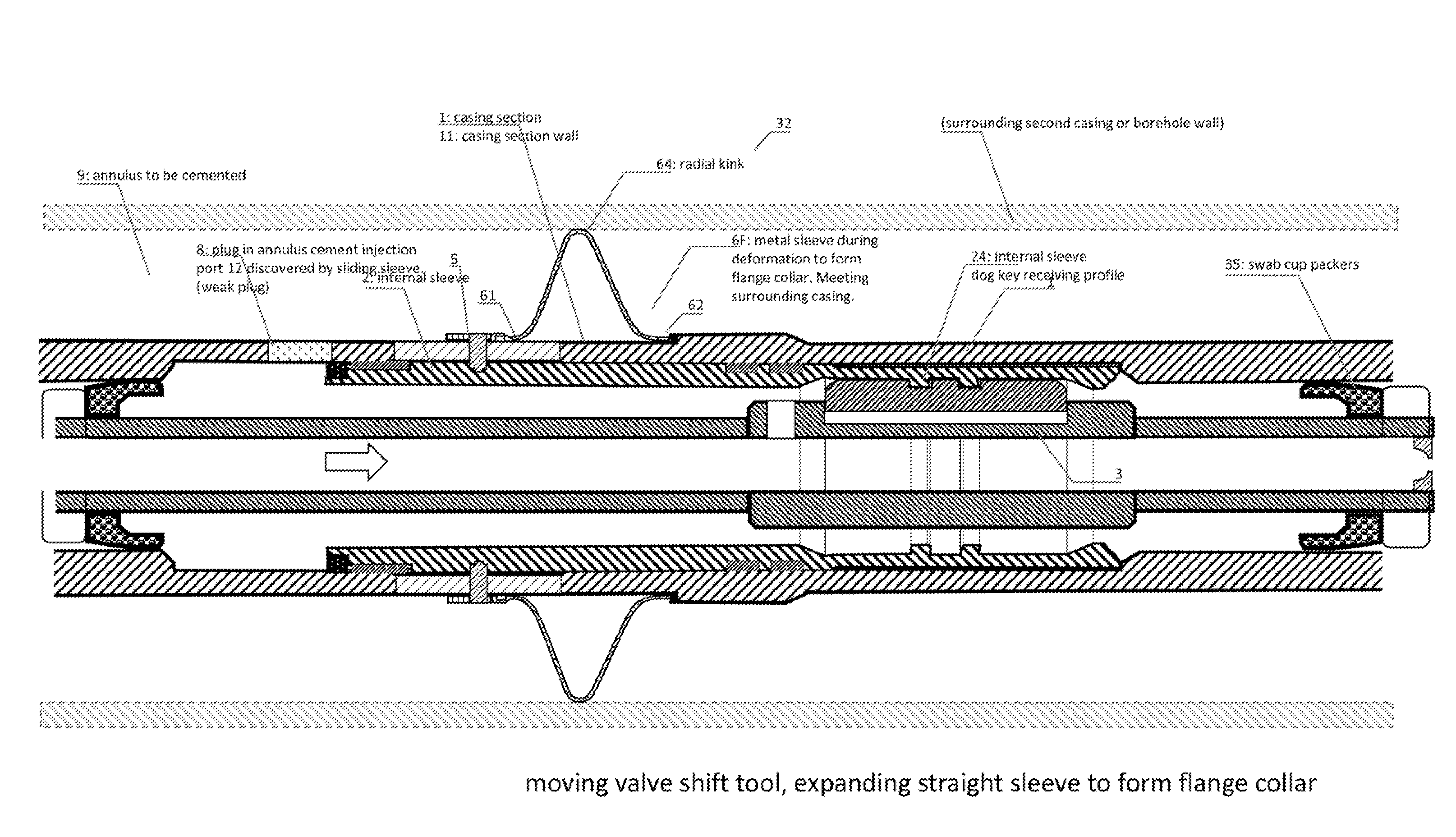
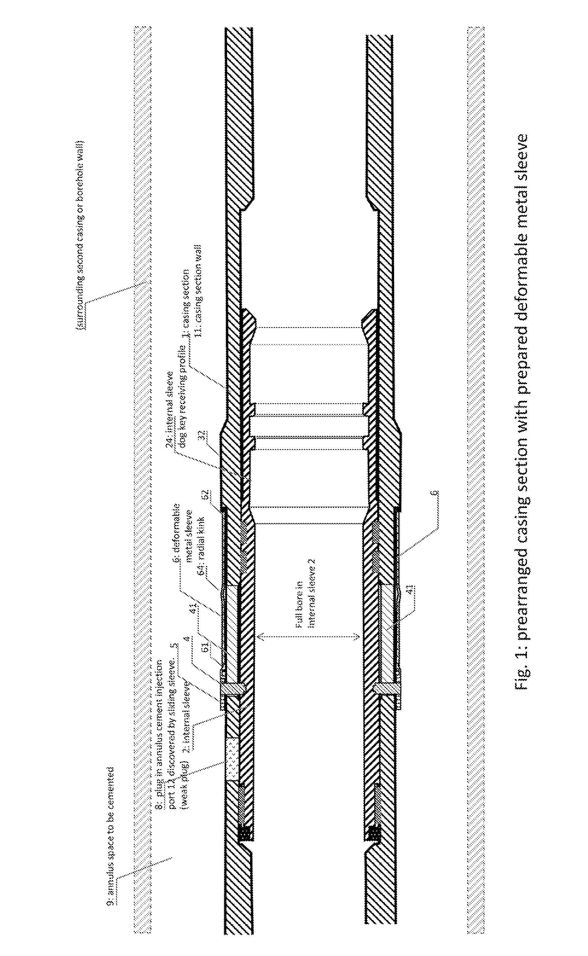
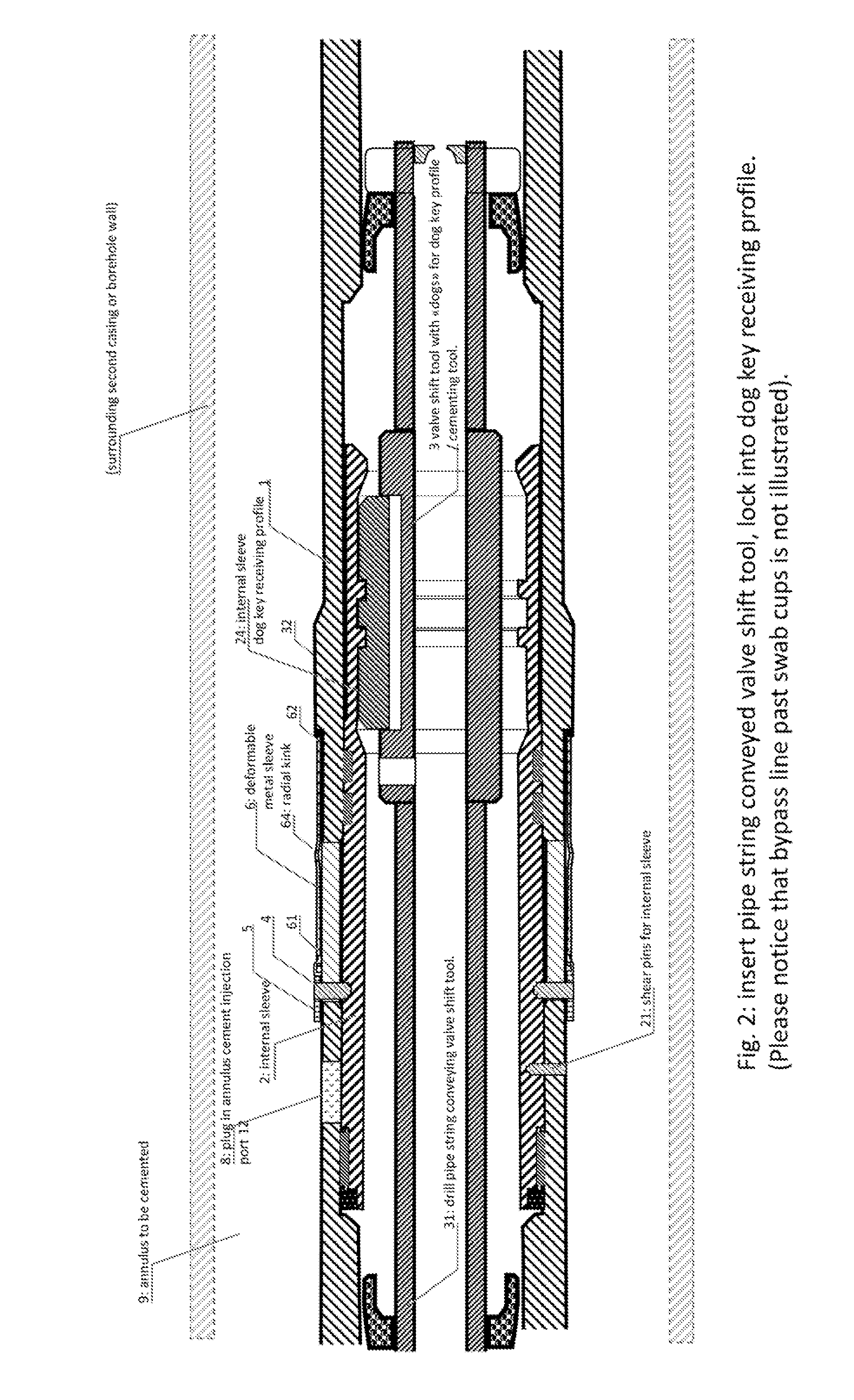
[0037]The invention is a casing annulus cement foundation system comprising:[0038]A casing section (1) comprising an internal sleeve (2) arranged for being manipulated by a conveyed shift tool (3) exerting a force for translating said internal sleeve (2) in an axial direction of said casing section (1). The shift tool (3) is drill pipe string conveyed in the described embodiment of the invention. The internal sleeve (2) is provided with one or more radially directed bolts (4) extending through corresponding axial-parallel slots (41) through the casing wall (11) of said casing section (1) and fixed to a corresponding sliding casing-external sleeve (5). In other words, the internal sleeve (2) is connected to the external casing sleeve (5) via bolts (4) through the casing section (1) wall (11), and the bolts may slide in axially directed ...


PUM


Abstract

A method for forming a flange collar constituting a cement foundation in a casing annulus, includes the steps of installing a casing section comprising an internal sleeve axially displaceable by a conveyed tool for opening a casing cementing outlet; the internal sleeve connected through radial bolts through axial-parallel slots through the casing wall to a casing-external sleeve, the casing-external sleeve abutting against a first edge of a deformable metal sleeve having its opposite, second end abutting axially against a radial shoulder on the casing section; using the drill pipe conveyed tool for axially displacing the internal sleeve thus forcing the external sleeve to deforming the metal sleeve to a radially extending flange collar radially extending across the casing annulus, and ejecting cement via the casing cementing outlet to the annulus, allowing the cement to distribute above the formed radially extending flange collar, and allowing the cement to settle in the annulus.

Description

FIELD OF THE INVENTION[0001]The present invention relates to the technical field of petroleum well construction. More specifically, the invention relates to a tool for cementing in the annulus outside a casing pipe in the well. The annulus may be between the casing and a surrounding borehole wall which shall be cemented. The annulus may also be between the inner casing and a surrounding second casing.[0002]The purpose of the present invention is to establish an annulus barrier and inject cement above it at a desired level in a casing annulus about a modified so-called Cflex-casing section as illustrated in an embodiment in FIG. 5. After cement injection into the annulus it is required to retract and close the sleeve valve and the tool, circulate to wash out remaining cement in the casing sleeve, and allow the cement in the annulus to set and harden. With the shift and cementing tool pulled out of hole there remains a full bore passage past the now cemented casing section.BACKGROUND ...

Claims


Application Information

Patent Timeline
IPC IPC(8): E21B34/14E21B33/14
CPCE21B34/14E21B2034/007E21B33/14E21B33/128E21B33/1208E21B33/13E21B2200/06
Inventor BYBERG, ARVEB DSVIK, ARVE
Owner ARCHER OILTOOLS
Why Eureka
Try Eureka