Thermally-assisted magnetic recording head including a main pole and a plasmon generator

a magnetic recording and magnetic technology, applied in the field of magnetic recording heads, can solve the problems of increasing the coercivity of the recording medium, reducing the thermal stability of the magnetic field, and difficult to perform data writing with the existing magnetic head, so as to reduce the width of the track

Active Publication Date: 2016-07-21
HEADWAY TECH INC
View PDF1 Cites 9 Cited by
  • Summary
  • Abstract
  • Description
  • Claims
  • Application Information

AI Technical Summary

Benefits of technology

[0014]It is an object of the present invention to provide a thermally-assisted magnetic recording head with a reduced track width and a main pole ...

Problems solved by technology

Making the magnetic fine particles smaller, however, causes the problem that the magnetic fine particles drop in the thermal stability of magnetization.
However, increasing the anisotropic energy of the magnetic fine particles leads to an increase in coercivity of the recording medium, and this makes it difficult to perform data writing with existing magnetic heads.
However, since the heat resulting from near-field light spreads on the recording medium by conduction, the thermal spot size becomes l...

Method used


Image

  • Thermally-assisted magnetic recording head including a main pole and a plasmon generator
  • Thermally-assisted magnetic recording head including a main pole and a plasmon generator
  • Thermally-assisted magnetic recording head including a main pole and a plasmon generator

Examples


first embodiment

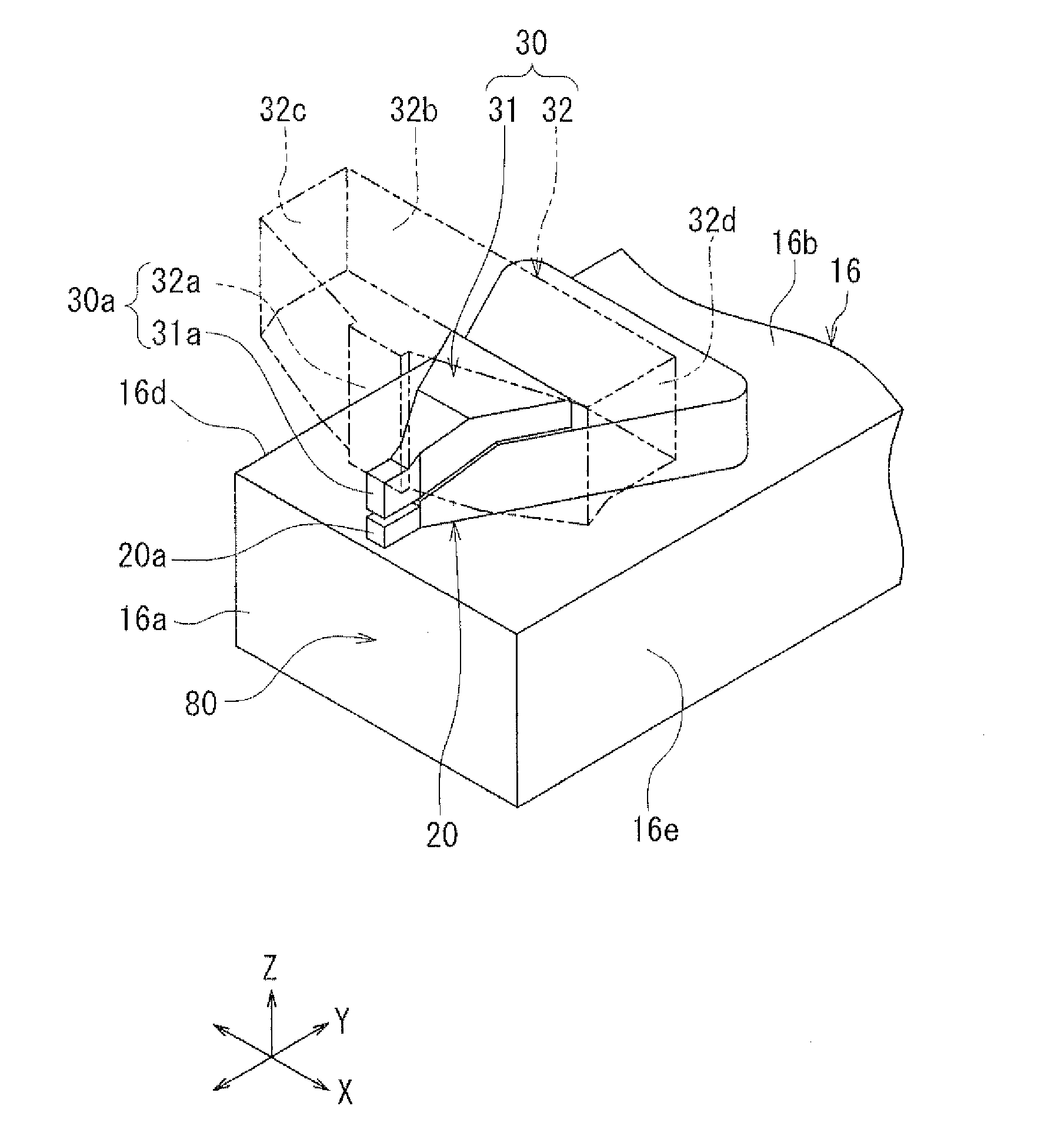
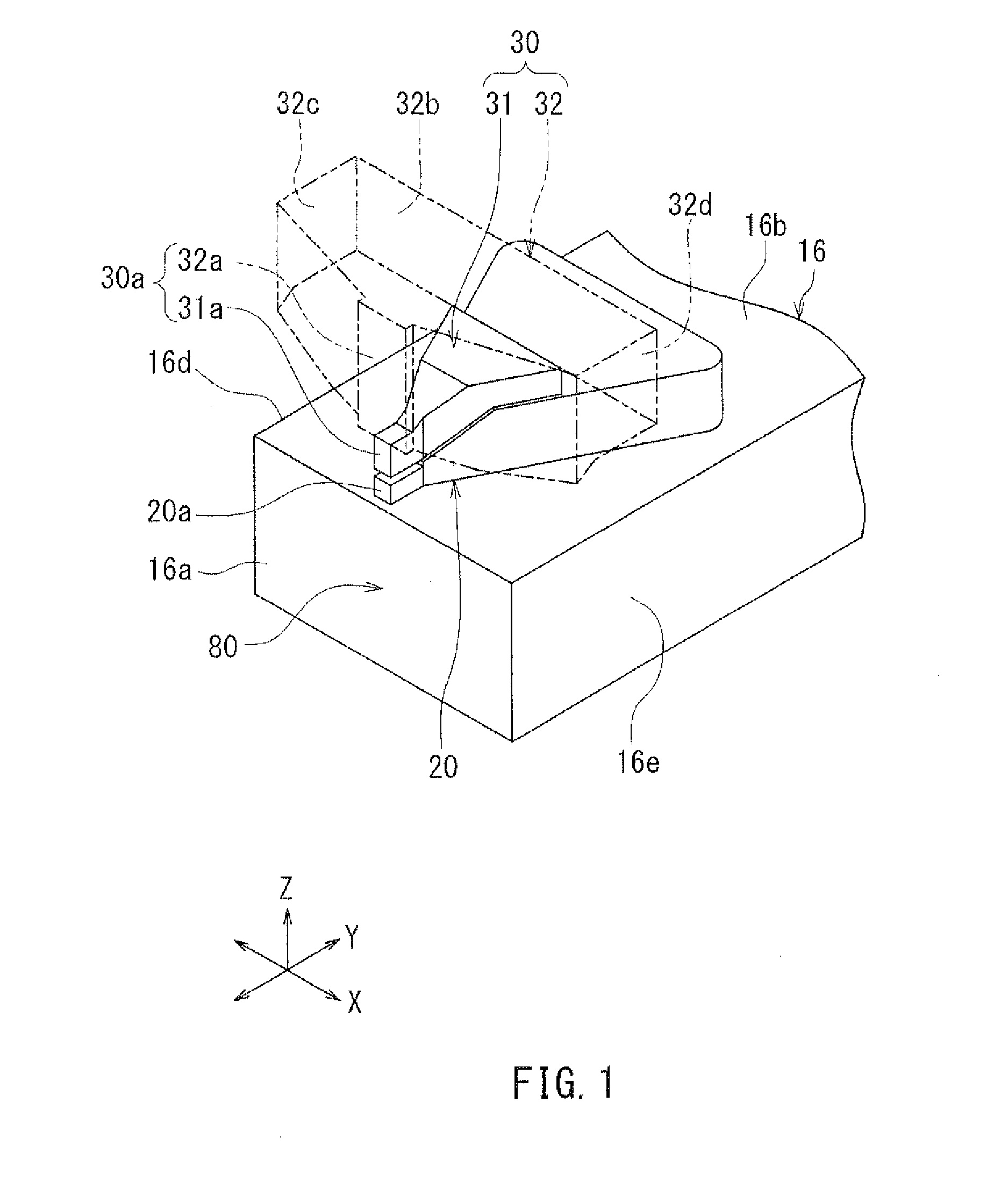
[0075]Preferred embodiments of the present invention will now be described in detail with reference to the drawings. First, reference is made to FIG. 1 to FIG. 8 to describe the configuration of a thermally-assisted magnetic recording head according to a first embodiment of the invention. FIG. 1 is a perspective view showing the main part of the thermally-assisted magnetic recording head. FIG. 2 is an enlarged perspective view of a part of FIG. 1. FIG. 3 is a front view showing the main part of the thermally-assisted magnetic recording head. FIG. 4 is a cross-sectional view showing the main part of the thermally-assisted magnetic recording head. FIG. 5 is a cross-sectional view showing the configuration of the thermally-assisted magnetic recording head. FIG. 6 is a front view showing the medium facing surface of the thermally-assisted magnetic recording head. FIG. 7 is a plan view showing a first layer of a coil of the present embodiment. FIG. 8 is a plan view showing a second layer...

second embodiment

[0168]A thermally-assisted magnetic recording head according to a second embodiment of the invention will now be described with reference to FIG. 24 and FIG. 25. FIG. 24 is a front view showing the main part of the thermally-assisted magnetic recording head according to the present embodiment. FIG. 25 is a cross-sectional view showing the main part of the thermally-assisted magnetic recording head according to the present embodiment.

[0169]The thermally-assisted magnetic recording head according to the present embodiment is configured differently than the first embodiment as described below. The thermally-assisted magnetic recording head according to the present embodiment includes a heat sink 46 provided around the plasmon generator 20 and the first layer 31 of the main pole 30. The heat sink 46 has the function of dissipating heat generated at the the plasmon generator 20 and heat transferred from the plasmon generator 20 to the first layer 31 outward from the plasmon generator 20 ...

third embodiment

[0187]A thermally-assisted magnetic recording head according to a third embodiment of the invention will now be described. In the present embodiment, the main pole 30 is constituted not by the first layer 31 and the second layer 32 but by a single magnetic layer. The shape and location of the main pole 30 of the present embodiment are the same as those of the main pole 30 of the first embodiment.

[0188]In the present embodiment, as shown in FIG. 3, the first edge E1 of the first end face portion 31a of the main pole 30 and the third edge E3 of the near-field light generating surface 20a are located on the first imaginary straight line L1, while the second edge E2 of the first end face portion 31a and the fourth edge E4 of the near-field light generating surface 20a are located on the second imaginary straight line L2, as in the first embodiment.

[0189]A method of manufacturing the thermally-assisted magnetic recording head according to the present embodiment will now be described with...


PUM


Abstract

A thermally-assisted magnetic recording head includes a main pole and a plasmon generator. The main pole has a front end face located in the medium facing surface. The plasmon generator has a near-field light generating surface located in the medium facing surface. The front end face of the main pole includes a first end face portion and a second end face portion. The second end face portion is located farther from the near-field light generating surface than is the first end face portion, and is greater than the first end face portion in width in the track width direction. The first end face portion and the near-field light generating surface are equal in width.

Description

BACKGROUND OF THE INVENTION[0001]1. Field of the Invention[0002]The present invention relates to a thermally-assisted magnetic recording head for use in thermally-assisted magnetic recording to write data on a recording medium with the coercivity thereof lowered by irradiating the recording medium with near-field light.[0003]2. Description of the Related Art[0004]Recently, magnetic recording devices such as magnetic disk drives have been improved in recording density, and thin-film magnetic heads and recording media of improved performance have been demanded accordingly. Among the thin-film magnetic heads, a composite thin-film magnetic head has been used widely. The composite thin-film magnetic head has such a structure that a read head unit including a magnetoresistive element (hereinafter, also referred to as MR element) for reading and a write head unit including an induction-type electromagnetic transducer for writing are stacked on a substrate. In a magnetic disk drive, the th...

Claims


Application Information

Patent Timeline
IPC IPC(8): G11B7/1387G11B5/48G11B5/127G11B5/17
CPCG11B7/1387G11B5/17G11B2005/0021G11B5/1272G11B5/4866G11B5/314G11B5/012G11B5/127G11B5/6088
Inventor SASAKI, YOSHITAKAITO, HIROYUKITANEMURA, SHIGEKIMAMIYA, HIDEOARAKI, HIRONORITOMITA, SEIICHIRO
Owner HEADWAY TECH INC
Why Eureka
Try Eureka