
High capacity sector mount

a sector mount and high-capacity technology, applied in the field of high-capacity sector mounts, can solve the problems of sector frame mounting failure, increased stress on the tower legs, etc., and achieve the effects of reducing the amount of time required to install the frame structure, reducing overall weight, and reducing epa

Inactive Publication Date: 2016-07-21
COMMSCOPE TECH LLC
View PDF3 Cites 14 Cited by
  • Summary
  • Abstract
  • Description
  • Claims
  • Application Information

AI Technical Summary

Benefits of technology

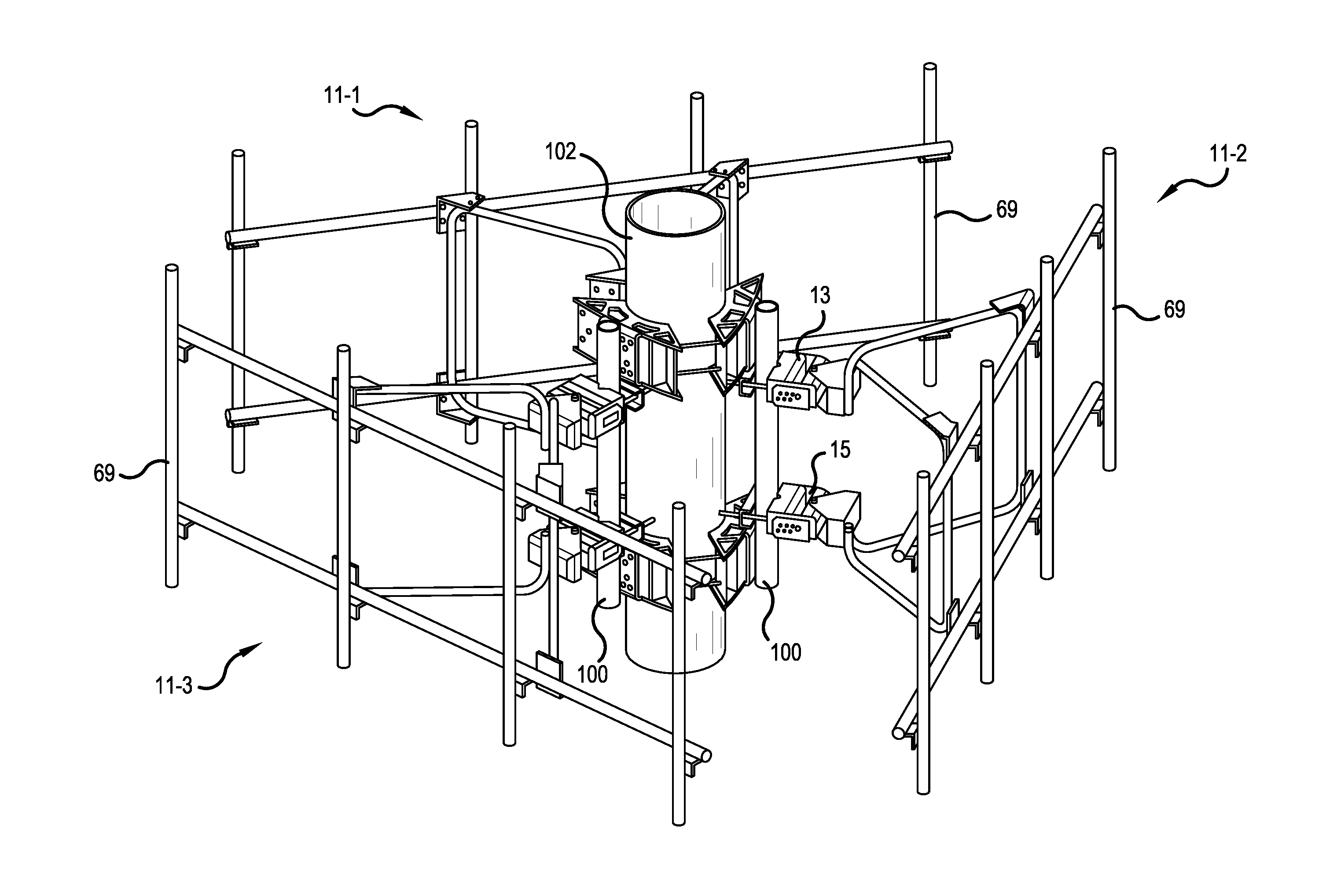
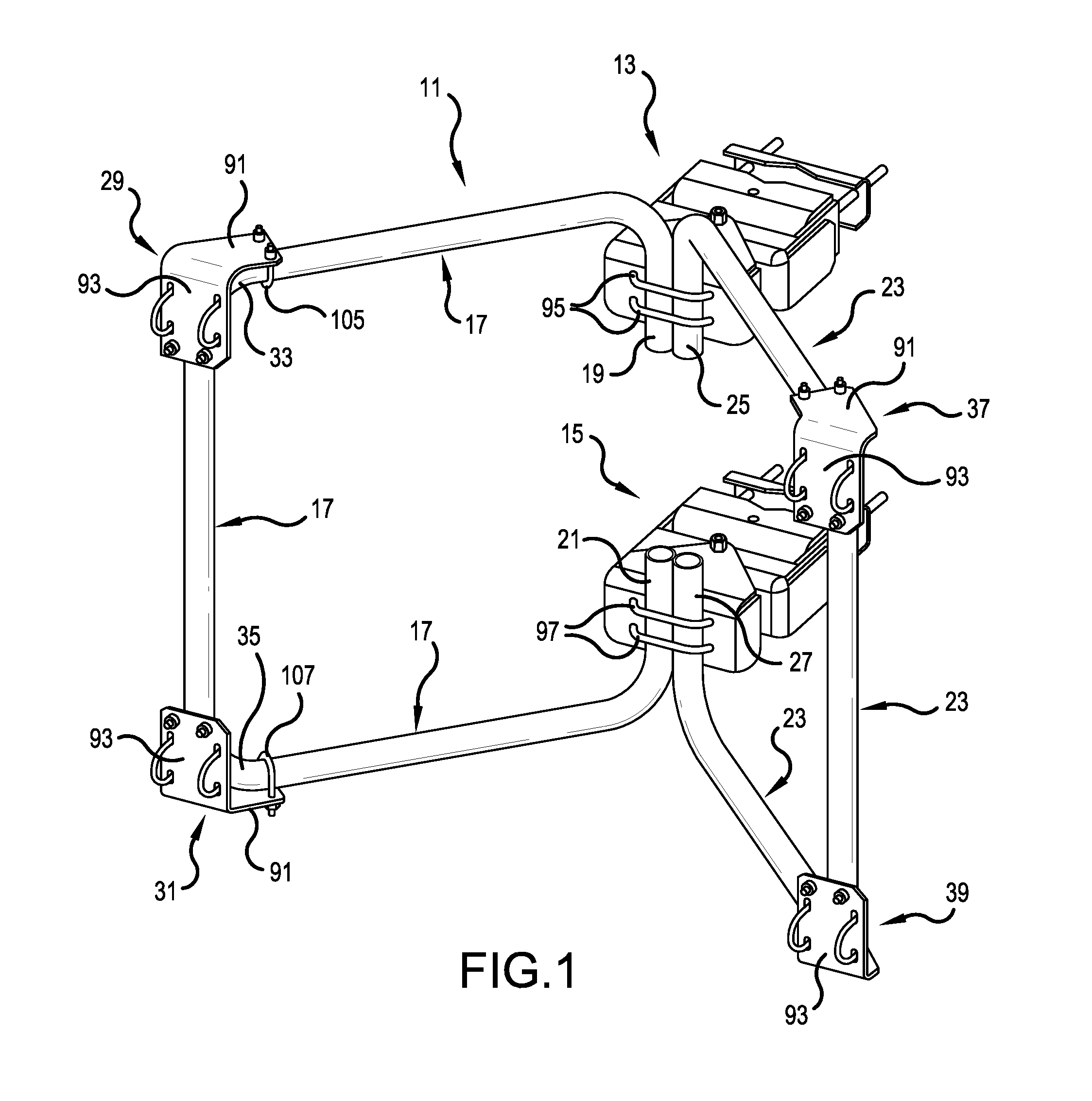
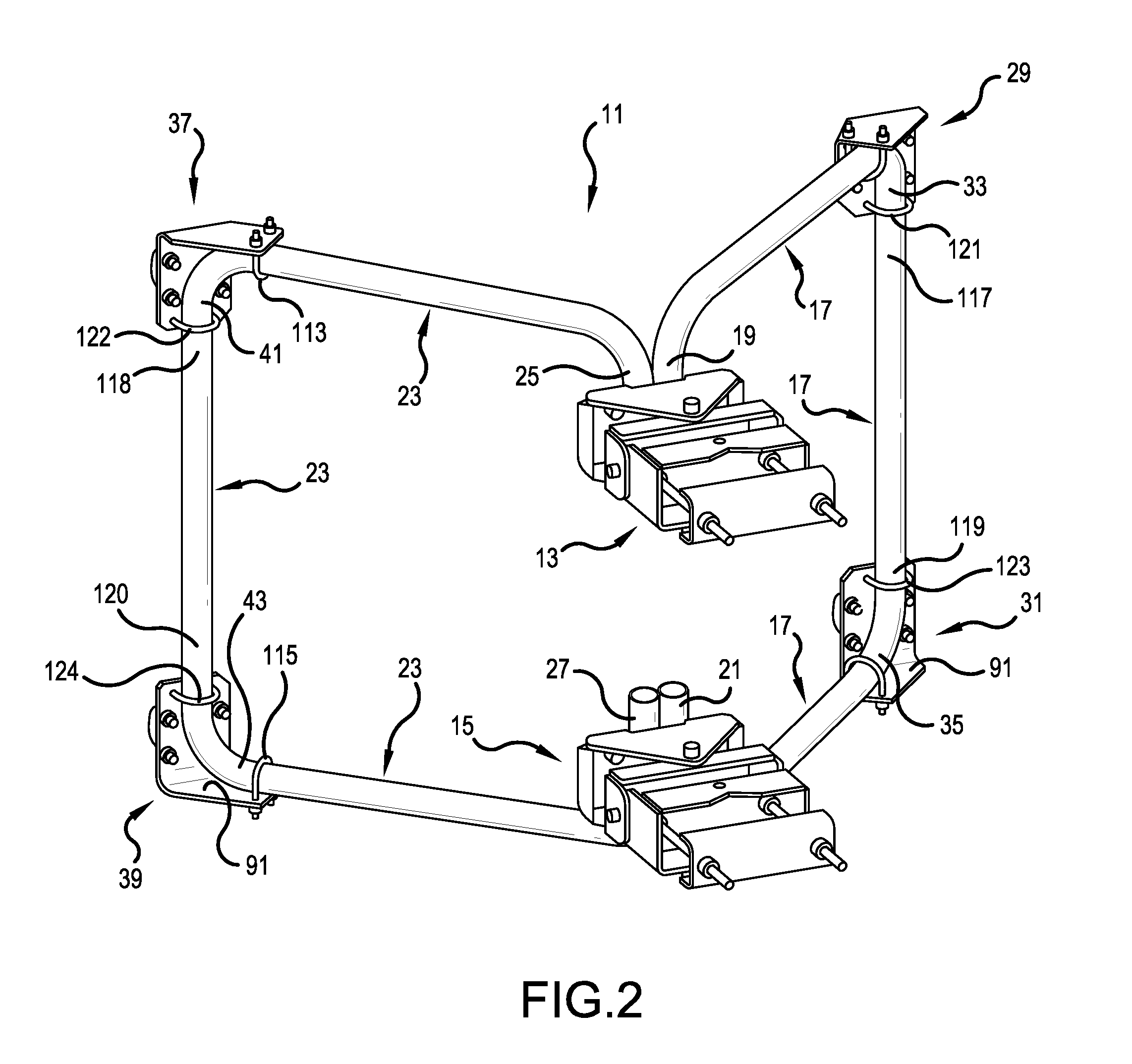
The new high capacity sector frame mount is a new product that Applicant has developed to meet the increased demand for more bandwidth. It is designed to support at least 1200 lbs. with a reduced overall EPA and weight. Compared to other mounts, it offers more equipment weight, but it is easier to install and requires less space on the tower. The use of two one-piece formed structural tubular frames eliminates the need for multiple parts and reduces installation time and exposure to wind loads, making it possible to install more equipment on the structure.

Problems solved by technology

More equipment is being mounted on existing structures causing increased stress to tower legs and in some cases sector frame mounting failures.

Method used


Image

  • High capacity sector mount
  • High capacity sector mount
  • High capacity sector mount

Examples


Embodiment Construction

[0035]The present invention now is described more fully hereinafter with reference to the accompanying drawings, in which embodiments of the invention are shown. This invention may, however, be embodied in many different forms and should not be construed as limited to the embodiments set forth herein; rather, these embodiments are provided so that this disclosure will be thorough and complete, and will fully convey the scope of the invention to those skilled in the art.

[0036]Like numbers refer to like elements throughout. In the figures, the thickness of certain lines, layers, components, elements or features may be exaggerated for clarity. Broken lines illustrate optional features or operations unless specified otherwise.

[0037]The terminology used herein is for the purpose of describing particular embodiments only and is not intended to be limiting of the invention. Unless otherwise defined, all terms (including technical and scientific terms) used herein have the same meaning as c...


PUM


Abstract

An antenna mount includes first and second tower mounting brackets. A first frame has first and second portions attached to the first and second tower mounting brackets, respectively. A second frame has third and fourth portions attached to the first and second tower mounting brackets, respectively. First and second equipment brackets are attached to the first frame, and third and fourth equipment brackets are attached to the second frame. Optionally, the first and second frames may each be formed as a one-piece continuous bent tube. Optionally, the first portion and the third portion are located side-by-side and clamped to the first tower bracket by a same first clamp, and the second portion and the fourth portion are located side-by-side and clamped to the second tower bracket by a same second clamp. Optionally, each equipment bracket has a frame face and an equipment face, wherein the frame face is orthogonal to the equipment face and extends in a direction which intersects a plane containing the equipment face at an angle of approximately 10 to 80 degrees.

Description

[0001]This application claims the benefit of U.S. Provisional Application No. 62 / 104,898, filed Jan. 19, 2015, which is herein incorporated by reference.BACKGROUND OF THE INVENTION[0002]1. Field of the Invention[0003]The present invention relates to a structure, e.g., a metal or steel structure, for supporting radios, antennas and / or similar equipment on a tower.[0004]2. Description of the Related Art[0005]Background art can be seen in U.S. Pat. Nos. 5,920,291, 7,086,207, 7,113,145, 7,466,286 and U.S. Published Patent Application No. 2007 / 0261355, each of which is herein incorporated by reference.SUMMARY OF THE INVENTION[0006]With increased demand for more wireless communication, the number of radio and antenna units that a tower traditionally supports has increased and is expected to continue to increase. New towers will need to be designed to support greater numbers of antenna and radio units, while existing towers are retrofitted to support more units and effort is made to fully ...

Claims


Application Information

Patent Timeline
IPC IPC(8): H01Q1/12
CPCH01Q1/1228
Inventor SKREPCINSKI, ALAN J.MCFALL, MICHAEL S.ROVELL, KEVIN L.WILLIS, ALLEN D.
Owner COMMSCOPE TECH LLC
Learn More