Anechoic chamber box for storing electronic apparatus

an electronic apparatus and anechoic chamber technology, applied in the direction of electrical apparatus casings/cabinets/drawers, cooling/ventilation/heating modifications, antennas, etc., can solve the problems of inability to implement and inability to configure an anechoic chamber box for storing electronic apparatus, and achieve the effect of efficient discharge of heat generated

Active Publication Date: 2016-07-21
NTT RESONANT TECH
View PDF0 Cites 5 Cited by
  • Summary
  • Abstract
  • Description
  • Claims
  • Application Information

AI Technical Summary

Benefits of technology

[0026]According to the present invention having the structure described above, the storage racks stored in the storage container are pulled out in the first direction and the desirable storage rack is then slid in the second direction if necessary, and the desirable storage shelf is further pulled out in the first direction so that the electronic apparatus can be put in/out. Moreover, the cable to the electronic apparatuses placed on the storage shelves is wired from the wiring device via the wiring passage provided on the inner side surface of the storage rack. Therefore, the cable is not an obstacle when the storage racks are to be pulled out in the first direction, when the desirable storage rack is to be slid in the second direction and when the desirable storage shelf is to be pulled out in the first direction. Consequently, a large number of electronic apparatuses can be stored in a saved space in the storage container and a desirable one of the electronic apparatuses can easily be put in/out.
[0027]According to the present invention, furthermore, both of the forward direction and the rearward direction in the first direction of the storage rack are set

Problems solved by technology

Although the storage tools described in the Patent Documents 1 to 6 are devised to effectively utilize a saved space without any waste, to easily put in/out a thing to be stored, and to perform wiring in the storage of an electronic apparatus, however, it is impossible to configure a box fo

Method used


Image

  • Anechoic chamber box for storing electronic apparatus
  • Anechoic chamber box for storing electronic apparatus
  • Anechoic chamber box for storing electronic apparatus

Examples


Embodiment Construction

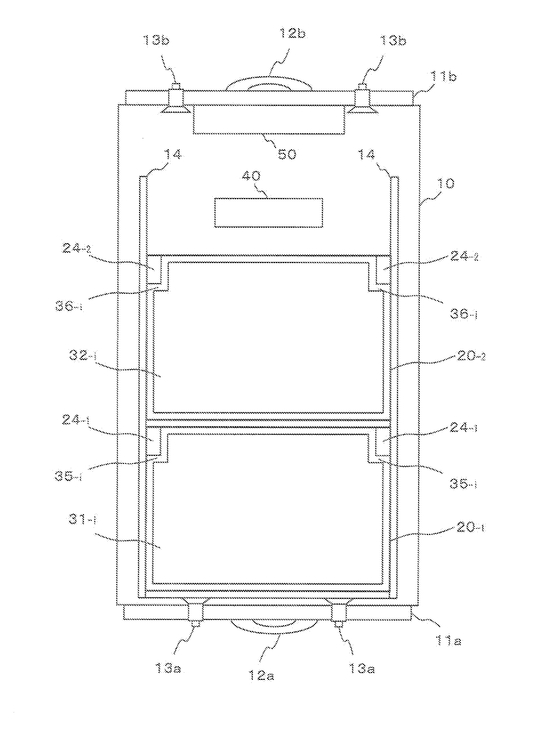
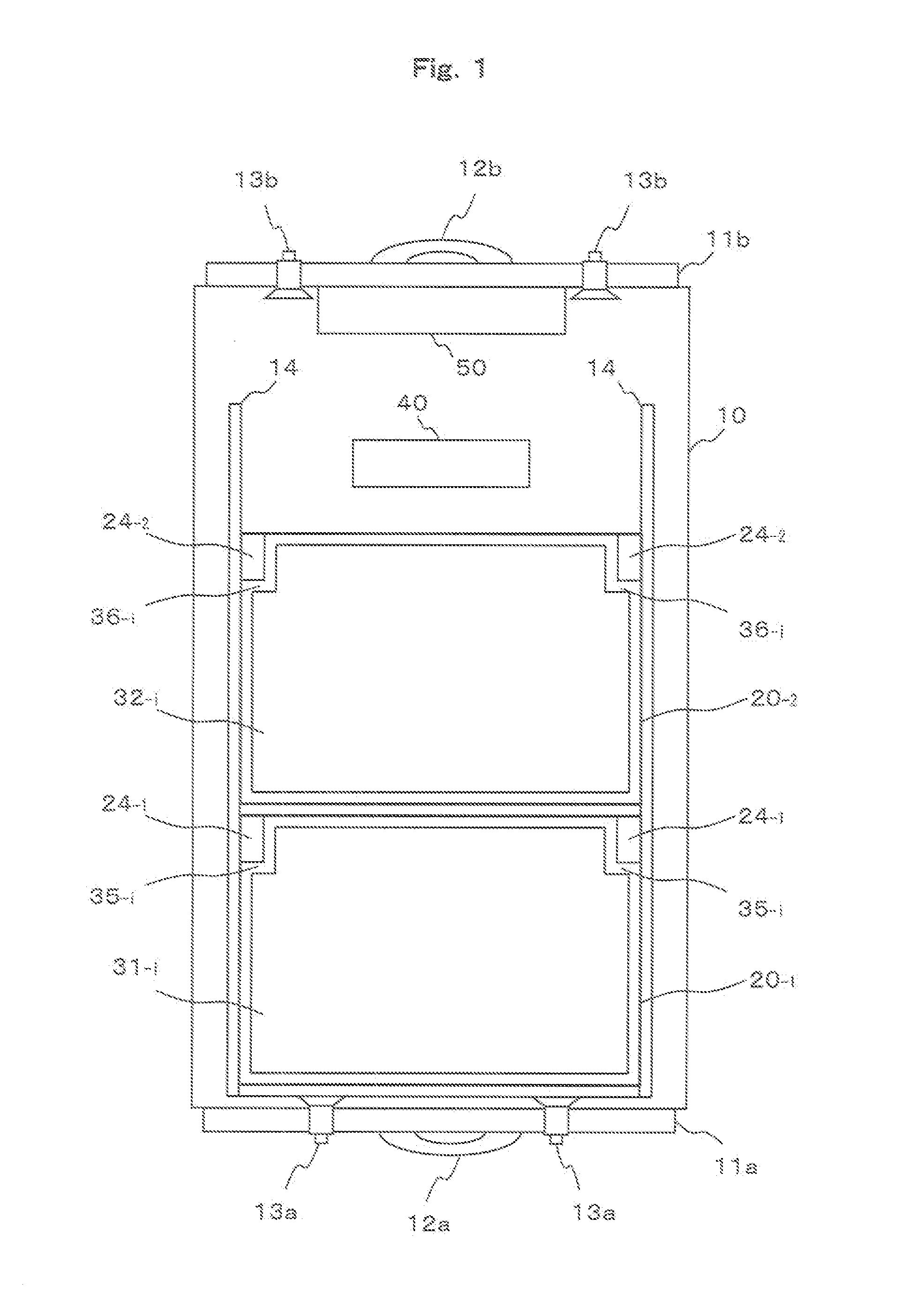
[0034]An embodiment according to the present invention will be described below with reference to the drawings. FIGS. 1 and 2 are schematic views showing an anechoic chamber box for storing electronic apparatuses according to the present embodiment as seen from above. Both of them virtually show a state in which an inner part is seen through from above. FIG. 1 shows a state in which storage racks to be described below are stored in a storage container, and FIG. 2 shows a state in which the storage racks are pulled out of the storage container and a storage shelf is further pulled out of the storage rack. It is assumed that a downward direction in the drawing indicates a front side and an upward direction in the drawing indicates a rear side.

[0035]Moreover, FIG. 3 is a schematic view showing the anechoic chamber box for storing electronic apparatuses according to the present embodiment as seen from a side, illustrating the state in which the storage racks are pulled out of the storage...


PUM


Abstract

Both a forward direction and a rearward direction of storage racks 20-1 and 20-2 are set to be opening portions 23 and intake and exhaust ducts 61-1, 61-2, 62-1 and 62-2 are provided on doors 11a and 11b in the forward direction and the rearward direction of a storage container 10. Consequently, a ventilation passage linked to an outside from a wall surface in the forward direction of the storage container 10 via a wall surface in the rearward direction is formed for each of storage shelves 31-i and 32-i of the storage racks 20-1 and 20-2 so that heat generated from an electronic apparatus can be efficiently discharged to an outside of the storage container 10, and furthermore, the storage container 10 itself is configured to be isolated electrically by a radio wave absorber so that a function of an anechoic chamber can also be ensured.

Description

TECHNICAL FIELD[0001]The present invention relates to an anechoic chamber box for storing electronic apparatuses and more particularly to a storage box capable of storing a plurality of electronic apparatuses which emit a radio wave to prevent the radio wave from leaking to an outside.BACKGROUND ART[0002]In recent years, a smart phone spreads rapidly in place of a portable telephone of a conventional type. As one of attractions of the smart phone, a user can freely download and utilize various applications (hereinafter referred to as smart phone applications).[0003]However, the smart phone is provided with various OS such as Android (a registered trademark), iPhone iOS (iPhone is a registered trademark), BlackBerry OS (BlackBerry is a registered trademark), Windows Phone 8 (Windows Phone is a registered trademark) and the like, and models are increased more greatly than before. Such an environment is a great worry to traders engaged in development or verification of the smart phone ...

Claims


Application Information

Patent Timeline
IPC IPC(8): H05K9/00H05K7/20H01Q17/00H05K5/02
CPCH05K9/0007H01Q17/00H05K7/20145H05K5/0247H05K9/0069
Inventor MORIMOTO, KYOHEIKURISHIMA, TOSHIYATSUNDA, KAZUYA
Owner NTT RESONANT TECH
Why Eureka
Try Eureka