Supercharge Your Innovation With Domain-Expert AI Agents!

Interspinous process implant having deployable anchor blades

a technology of interspinous process and implant, which is applied in the field of surgical implants, can solve the problems of inability to carry out a fusion device, pain and numbness in the back and legs, and the prior art device still requires an incision to access the spinal column

Inactive Publication Date: 2016-07-28
SPINAL SIMPLICITY
View PDF4 Cites 0 Cited by
  • Summary
  • Abstract
  • Description
  • Claims
  • Application Information

AI Technical Summary

Benefits of technology

The present invention is a new and useful interspinous process implant that can be percutaneously implanted. It includes an elongated body with a longitudinal axis, an interior cavity, and an anchor collar and bronch blades that are moveable within the body. The anchor collar is locked in position using a locking ring. The invention allows for the modulation of the interspinous process space, providing a therapeutic effect for the treatment of various spinal conditions.

Problems solved by technology

Over time, the ligaments and bone that surround the spinal canal can thicken and harden, resulting in a narrowing of the spinal canal and compression of the spinal cord or nerve roots.
This condition is called spinal stenosis, which results in pain and numbness in the back and legs, weakness and / or a loss of balance.
While some patients may experience relief from symptoms of spinal stenosis with such treatments, many do not, and thus turn to surgical treatment.
However, implantation and deployment of this prior art device still requires an incision to access the spinal column.
This implant functions as a spacer between two adjacent spinous processes, but it is not designed to stabilize the spinous process and can migrate over time.

Method used


Image

  • Interspinous process implant having deployable anchor blades
  • Interspinous process implant having deployable anchor blades
  • Interspinous process implant having deployable anchor blades

Examples


Embodiment Construction

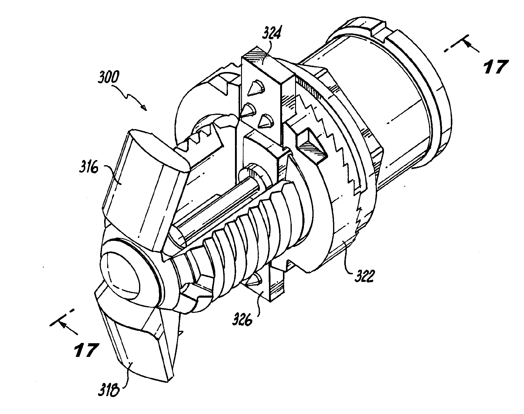
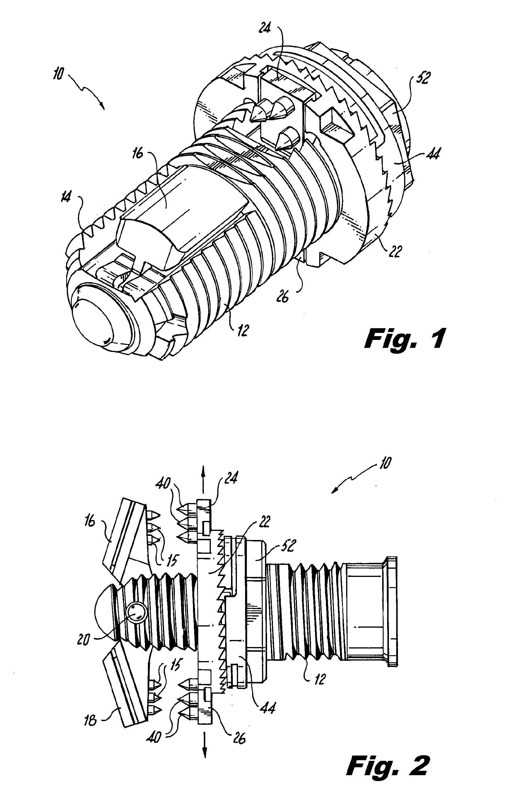
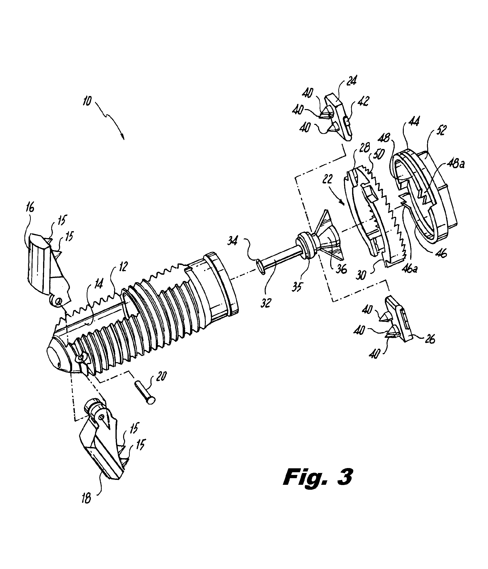
[0043]Referring now to the drawings wherein like reference numerals identify similar structural features or aspects of the surgical implants disclosed herein, there is illustrated in FIG. 1 a preferred embodiment of an interspinous process implant constructed in accordance with a preferred embodiment of the subject invention and designated generally by reference numeral 10.

[0044]Referring to FIGS. 1-3, implant 10 includes an elongated threaded body 12 which is dimensioned and configured for percutaneous interspinous process implantation by a physician. The threaded body 12 has a longitudinal axis, an interior cavity 14 and opposed proximal and distal end portions. Here and throughout the specification distal refers to the forward end of the device and proximal refers to the rearward end of the device.

[0045]A pair of anchor wings 16, 18 are operatively associated with the distal end portion of the body 12 and are mounted for pivotal movement about a pin 20 extending perpendicular to ...


PUM


Abstract

An interspinous process implant is disclosed that includes a body defining a longitudinal axis, an interior cavity and opposed proximal and distal end portions, a pair of anchor wings operatively associated with the distal end portion of the body and mounted for pivotal movement relative to the longitudinal axis of the body between a first position housed within the interior cavity of the body and a second position extending radially outwardly from the body, an anchor collar operatively associated with the proximal portion of the body and mounted for axial movement relative to the longitudinal axis of the body between a first position spaced apart from the anchor wings and a second position approximated with the anchor wings, a pair of anchor blades operatively associated with the anchor collar and mounted for movement between a first position housed at least partially within the interior cavity of the body and a second position extending radially outwardly from the anchor collar.

Description

CROSS-REFERENCE TO RELATED APPLICATIONS[0001]This application is a continuation of U.S. patent application Ser. No. 13 / 940,868, filed Jul. 12, 2013, which claims the benefit of and priority to U.S. Provisional Patent Application Ser. No. 61 / 749,595, filed Jan. 7, 2013, these applications are incorporated herein by reference in their entirety.BACKGROUND OF THE INVENTION[0002]1. Field of the Invention[0003]The subject invention is directed to surgical implants, and more particularly, to a percutaneous interspinous process implant and fusion device.[0004]2. Description of Related Art[0005]The spine consists of a column of twenty-four vertebrae that extend from the skull to the hips. Discs of soft tissue are disposed between adjacent vertebrae. In addition, the spine encloses and protects the spinal cord, defining a bony channel around the spinal cord, called the spinal canal. There is normally a space between the spinal cord and the borders of the spinal canal so that the spinal cord a...

Claims


Application Information

Patent Timeline
Patent Type & Authority Applications(United States)
IPC IPC(8): A61B17/70
CPCA61B17/7065
Inventor HESS, HAROLDFROCK, ADAMFROCK, MELISSAMOSELEY, TODDROGERS, ADAMHESS, JONATHAN
Owner SPINAL SIMPLICITY
Features
  • R&D
  • Intellectual Property
  • Life Sciences
  • Materials
  • Tech Scout
  • Unparalleled Data Quality
  • Higher Quality Content
  • 60% Fewer Hallucinations
Learn More