
Tyre-changing machine

a technology of tyres and cylinders, which is applied in the direction of tyre repair, vehicle components, transportation and packaging, etc., can solve the problems of damage to the rim, high cost of linear actuators, and high cost of high performance linear actuators

Inactive Publication Date: 2016-07-28
SICAM SRL
View PDF8 Cites 0 Cited by
  • Summary
  • Abstract
  • Description
  • Claims
  • Application Information

AI Technical Summary

Benefits of technology

The present invention provides a new type of tyre-changing machine that has the following benefits over previous designs: it is simple, easy, and affordable to use. The technical effects of this new invention are to overcome the limitations of previous designs and provide an effective and easy-to-use machine for changing tires.

Problems solved by technology

The bending moments produced by the stresses in correspondence to the arm and the post, and in particular to the hinge, make it necessary to use a linear actuator with a high performance, which as is well known, is expensive.
Such moments can result in damage being caused to the rim.

Method used


Image

  • Tyre-changing machine
  • Tyre-changing machine
  • Tyre-changing machine

Examples


Embodiment Construction

[0027]The main aim of the present invention is to provide a tyre-changing machine wherein, during use, the bending moments acting in correspondence to the post hinge and in correspondence to the rim are less than those of prior art.

[0028]Another object of the present invention is to provide a tyre-changing machine which can overcome the above mentioned drawbacks of the prior art in the ambit of a simple, rational, easy and effective to use as well as affordable solution.

[0029]The above mentioned objects are achieved by the present tyre-changing machine made according to claim 1.

BRIEF DESCRIPTION OF THE DRAWINGS

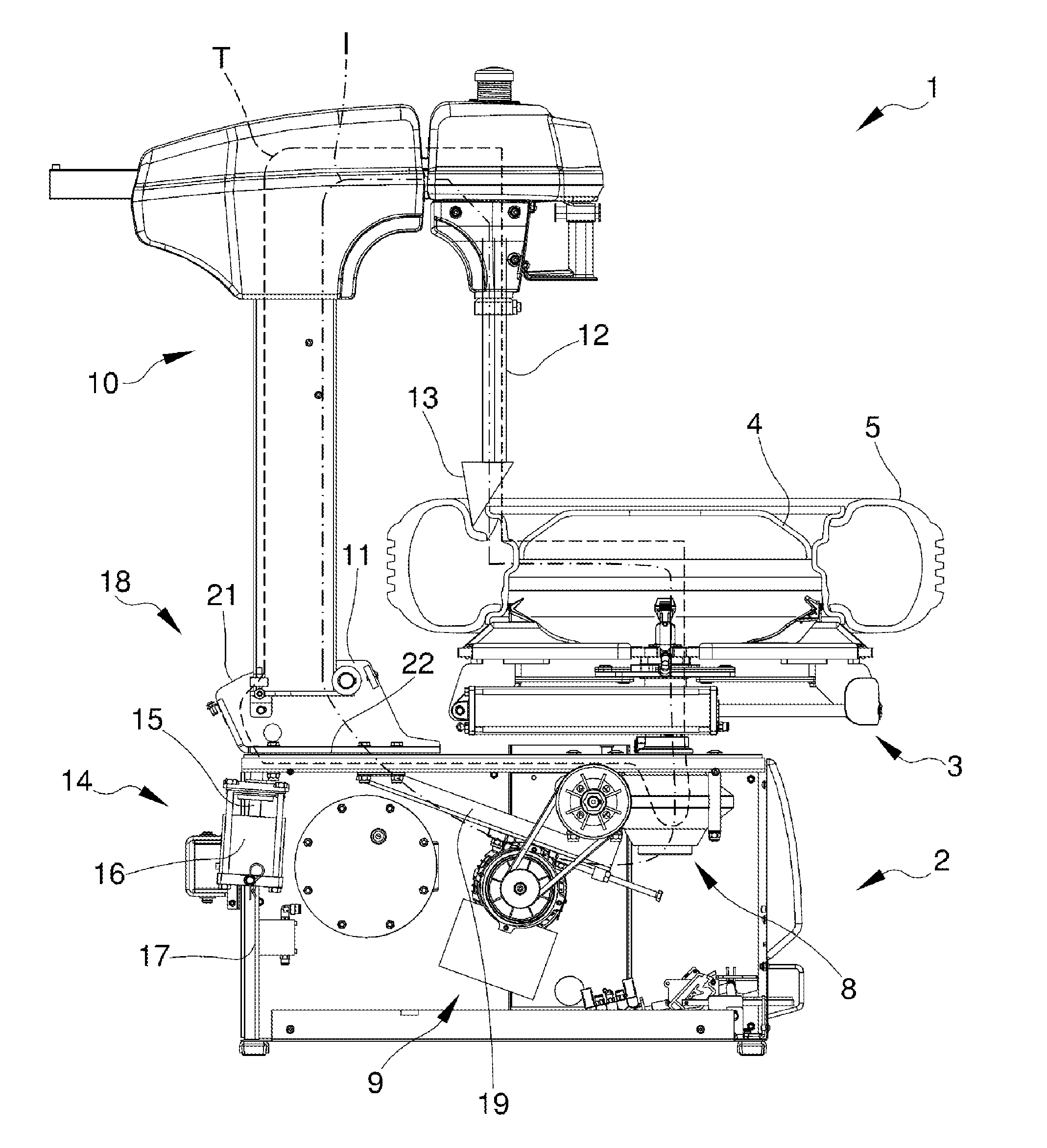
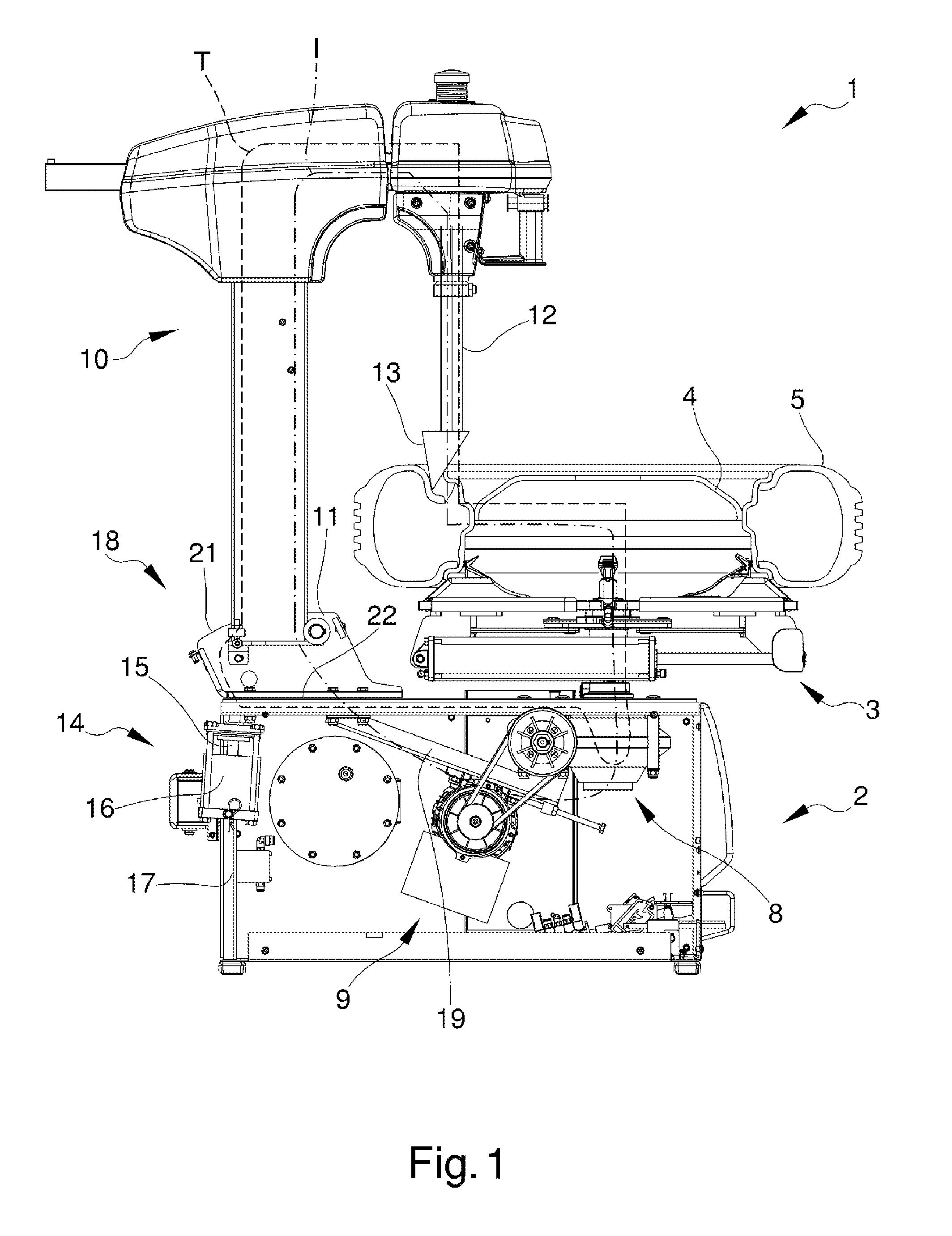
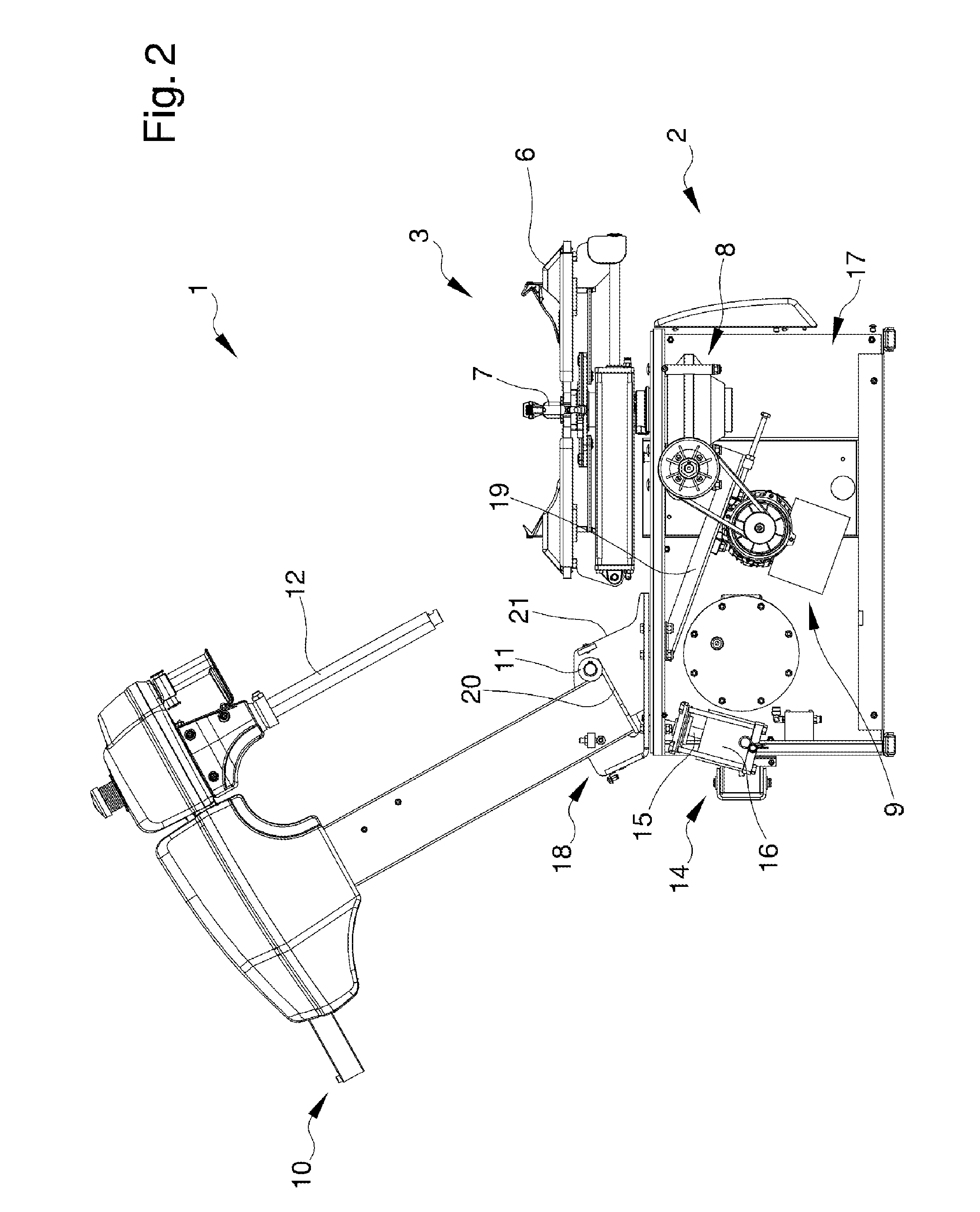
[0030]Other characteristics and advantages of the present invention will become better evident from the description of a preferred, but not exclusive, embodiment of a tyre-changing machine, illustrated by way of an indicative, but not limitative example in the accompanying drawings in which:

[0031]FIG. 1 is a vertical sectional view of the tyre-changing machine according to the...


PUM


Abstract

The tyre-changing machine comprises: a base structure which can rest on the ground; a gripping and rotation unit, suitable for gripping the rim of a wheel and placing it in rotation, mounted on a front part of the structure; a supporting post, arranged at the rear of the unit, connected to the structure by means of a hinge arranged in correspondence to a front part of the post facing the unit, the post being rotatable around the hinge between a work position, wherein it is closer to the unit, and a disengagement position, wherein it is tilted to the rear and is farther from the unit; and a tool-carrying arm fitted on the post suitable for carrying a tool to fit / remove a tyre onto / from the rim.

Description

TECHNICAL FIELD[0001]The present invention relates to a tyre-changing machine.BACKGROUND ART[0002]The use is known of tyre-changing machines for the removal and fitting of a tyre from the relative rim to repair or replace the tyre itself.[0003]A known type of machine comprises a base having a wheel gripping and rotation unit, a supporting post positioned upright from the base and a tool-carrying arm mounted on the post and suitable for moving vertically and horizontally.[0004]The arm bears a tool for removing or fitting the tyre.[0005]The removal tool is suitable for gripping the bead of the tyre to raise and remove it above an annular flange of the rim.[0006]In use, after a preliminary tyre bead breaking phase, an operator positions and locks the wheel on the gripping and rotation means.[0007]The tool is then moved towards the wheel, until it abuts and presses the side of the tyre, introducing one of its extremities, usually hooked, between the tyre bead and the rim.[0008]Subsequen...

Claims


Application Information

Patent Timeline
Patent Type & Authority Applications(United States)
IPC IPC(8): B60C25/138B60C25/05
CPCB60C25/138B60C25/0539B60C25/0545
Inventor DRESSLER, BJOERNVESCOVINI, MARCOGILOCCHI, ALESSANDRO
Owner SICAM SRL
Learn More