
High power connector and related assembly method

a technology of connectors and connectors, applied in the direction of printed circuit board receptacles, electrical apparatus construction details, transportation and packaging, etc., can solve the problems of complex assembly and electrical connection operations, complex positioning and electrical connection of these connectors, and complex container itsel

Active Publication Date: 2022-02-17
META SYST
View PDF14 Cites 0 Cited by
  • Summary
  • Abstract
  • Description
  • Claims
  • Application Information

AI Technical Summary

Benefits of technology

The present invention aims to simplify the assembly and electrical connection operations of high power connectors. By devoting a simplified and easy-to-use assembly method, the invention allows for overcoming the limitations of prior art within a cost-effective solution.

Problems solved by technology

However, the positioning and electrical connection of these connectors is complex.
For this purpose, it is necessary to make suitable access openings to be made on the container or to use long wirings that, given the currents involved, are not good for this type of application.
This makes the assembly and electrical connection operations complex.
Therefore, the container itself is more complex with inevitably higher production costs.

Method used


Image

  • High power connector and related assembly method
  • High power connector and related assembly method
  • High power connector and related assembly method

Examples


Embodiment Construction

[0009]The main aim of the present invention is to devise a high power connector and a related assembly method which allow the assembly and electrical connection operations to be simplified.

[0010]Another object of the present invention is to devise a high power connector and a related assembly method which allow overcoming the aforementioned drawbacks of the prior art within a simple, rational, easy, effective to use and affordable solution.

[0011]The objects set forth above are achieved by the present high power connector according to claim 1.

BRIEF DESCRIPTION OF THE DRAWINGS

[0012]Other characteristics and advantages of the present invention will become more evident from the description of a preferred but not exclusive embodiment of a high power connector and related assembly method, illustrated by way of an indicative example, not limited thereto, in the accompanying tables of drawings in which:

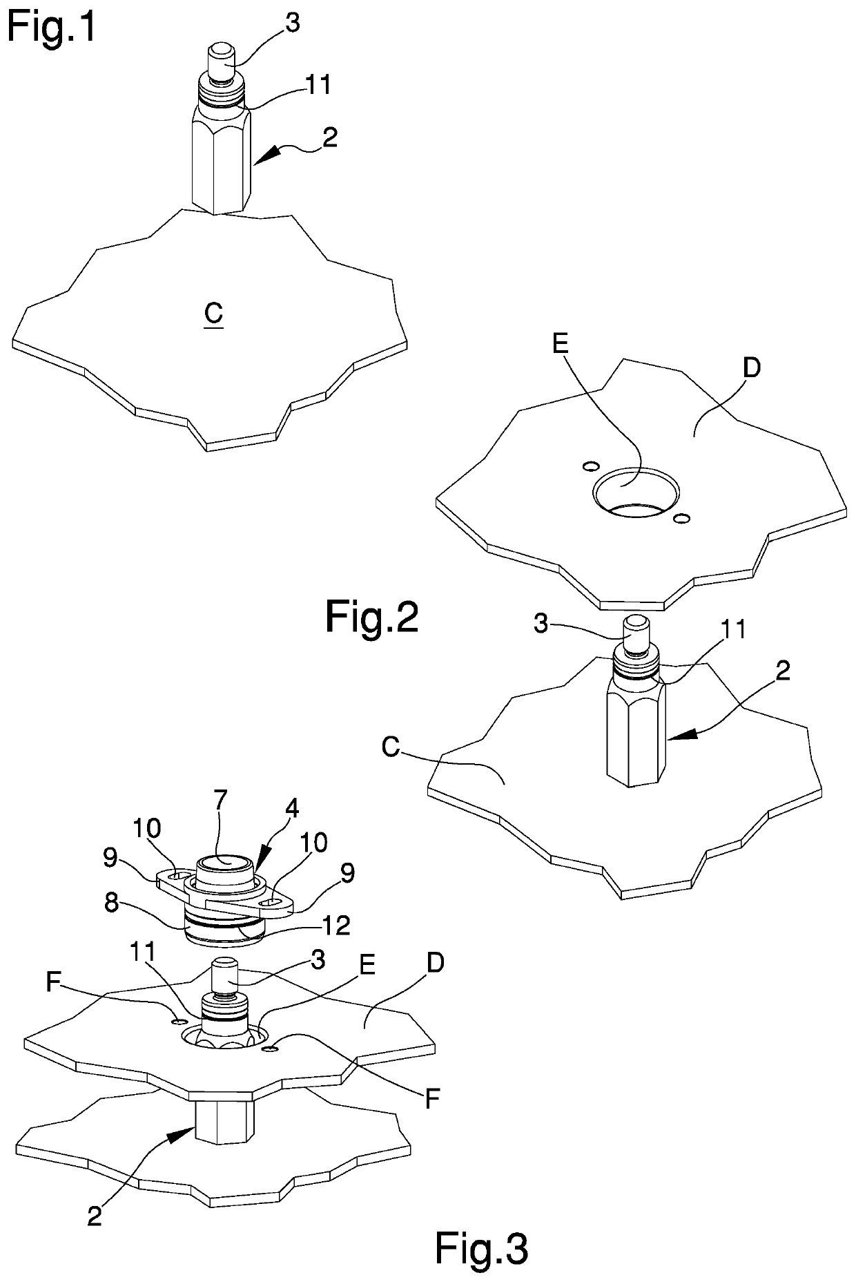
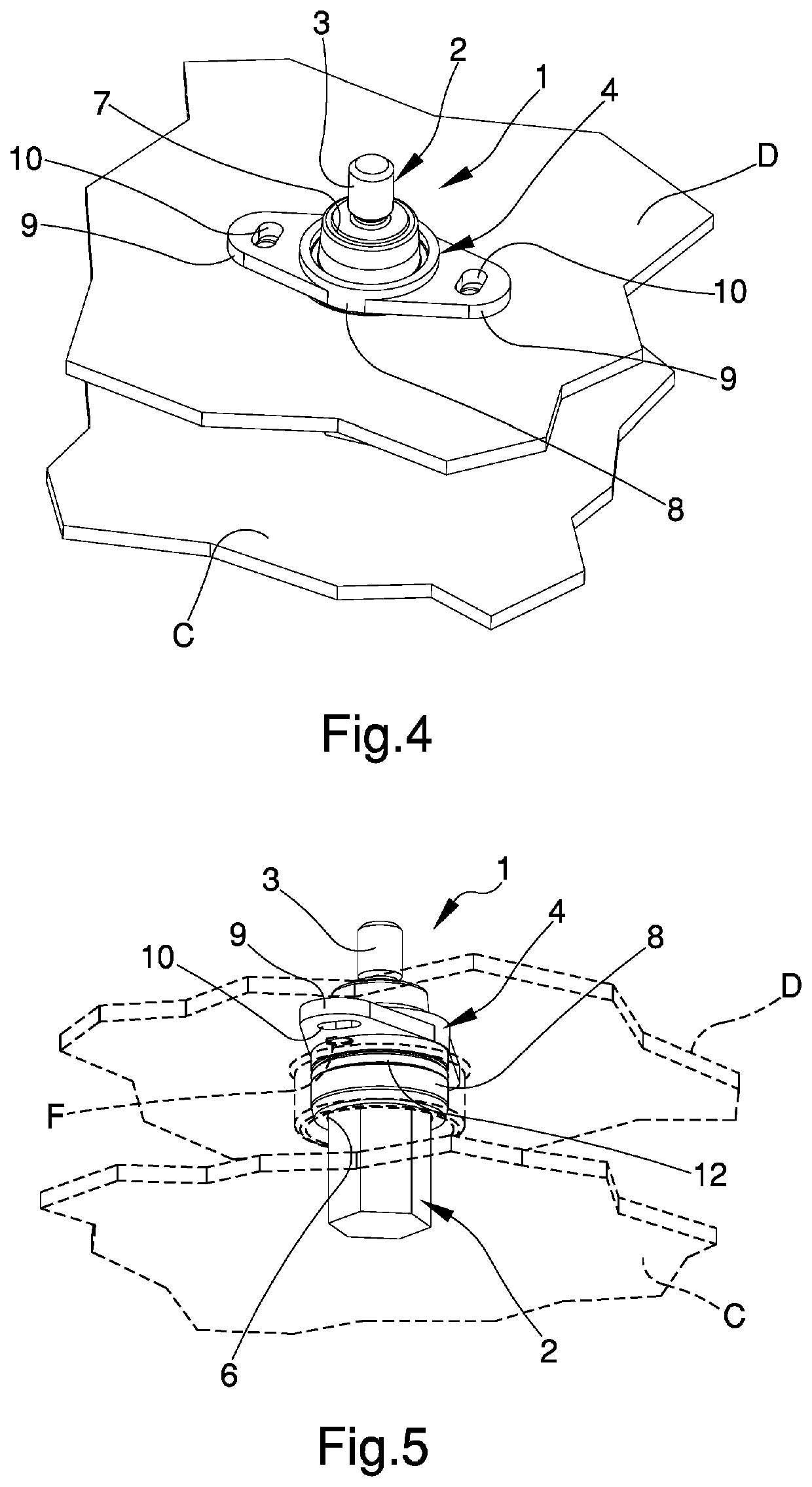
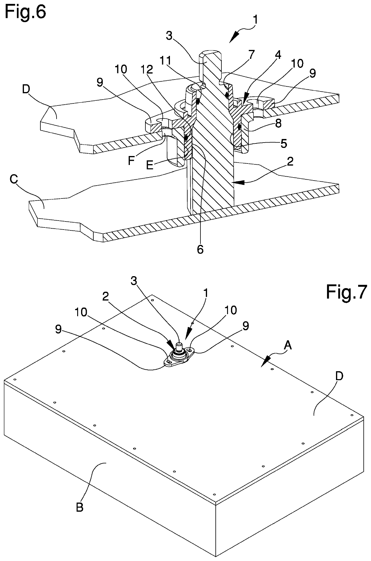
[0013]FIGS. 1 to 6 illustrate different steps of the assembly method of the connector acc...


PUM


Abstract

A high power connector comprises an electricity conductive element of substantially elongated conformation and provided with a first end portion electrically connectable to a power electronic circuit of a power electronic apparatus and with a second end portion provided with an electrical connection terminal, the conductive element being insertable inside a through opening made on the cover with said terminal facing outwards, wherein the connector comprises a locking element made of an electrically insulating material that can be coupled with the conductive element and fixable to the outer surface of the cover.

Description

TECHNICAL FIELD[0001]The present invention relates to a high power connector, usable in particular as an external connector in DC-DC converters, battery chargers or the like, and to the related assembly method.BACKGROUND ART[0002]The need is known to manufacture power electrical apparatuses provided with high power connectors accessible from the outside.[0003]For example, this need is particularly felt in the automotive sector, in particular with reference to the production of power electronic apparatuses installed on board electric or hybrid vehicles for the conversion of an input voltage / current into a suitable output voltage / current, such as OBC (On-Board Chargers) chargers or DC-DC converters.[0004]Such power electronic apparatuses generally comprise one or more power or control electronic boards, composed of one or more printed circuits, housed inside a suitable container. The container is hermetically sealed using a special cover.[0005]With reference to such apparatuses, the n...

Claims


Application Information

Patent Timeline
IPC IPC(8): H05K7/14
CPCH05K7/1432H05K7/1408H05K7/14329Y02T10/70
Inventor LASAGNI, CESARE
Owner META SYST
Learn More