Gas-electric propulsion system for an aircraft

a propulsion system and aircraft technology, applied in the direction of efficient propulsion technologies, air flow influencers, transportation and packaging, etc., can solve the problems of loss of operability or efficiency, non-uniform or distorted velocity profile of air entering the jet engine, and conventional turbofan jet engines,

Active Publication Date: 2016-07-28
GENERAL ELECTRIC CO
View PDF3 Cites 70 Cited by
  • Summary
  • Abstract
  • Description
  • Claims
  • Application Information

AI Technical Summary

Problems solved by technology

While this technique reduces the net drag by re-energizing the boundary layer downstream from the aircraft, the flow of air from the boundary layer entering the jet engine generally has a non-uniform or distorted velocity pro

Method used


Image

  • Gas-electric propulsion system for an aircraft
  • Gas-electric propulsion system for an aircraft
  • Gas-electric propulsion system for an aircraft

Examples


Embodiment Construction

[0020]Reference will now be made in detail to present embodiments of the invention, one or more examples of which are illustrated in the accompanying drawings. The detailed description uses numerical and letter designations to refer to features in the drawings. Like or similar designations in the drawings and description have been used to refer to like or similar parts of the invention. As used herein, the terms “first”, “second”, and “third” may be used interchangeably to distinguish one component from another and are not intended to signify location or importance of the individual components. The terms “upstream” and “downstream” refer to the relative direction with respect to fluid flow in a fluid pathway. For example, “upstream” refers to the direction from which the fluid flows, and “downstream” refers to the direction to which the fluid flows.

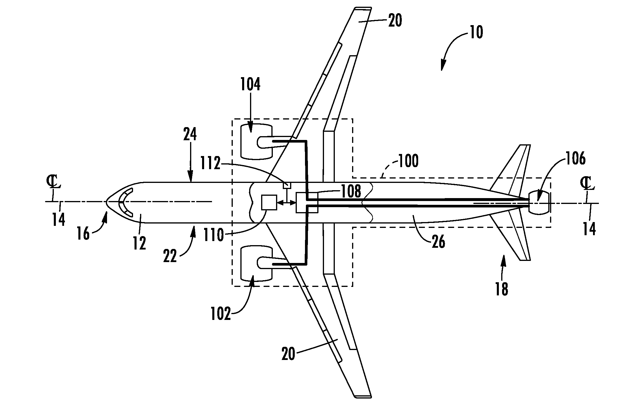
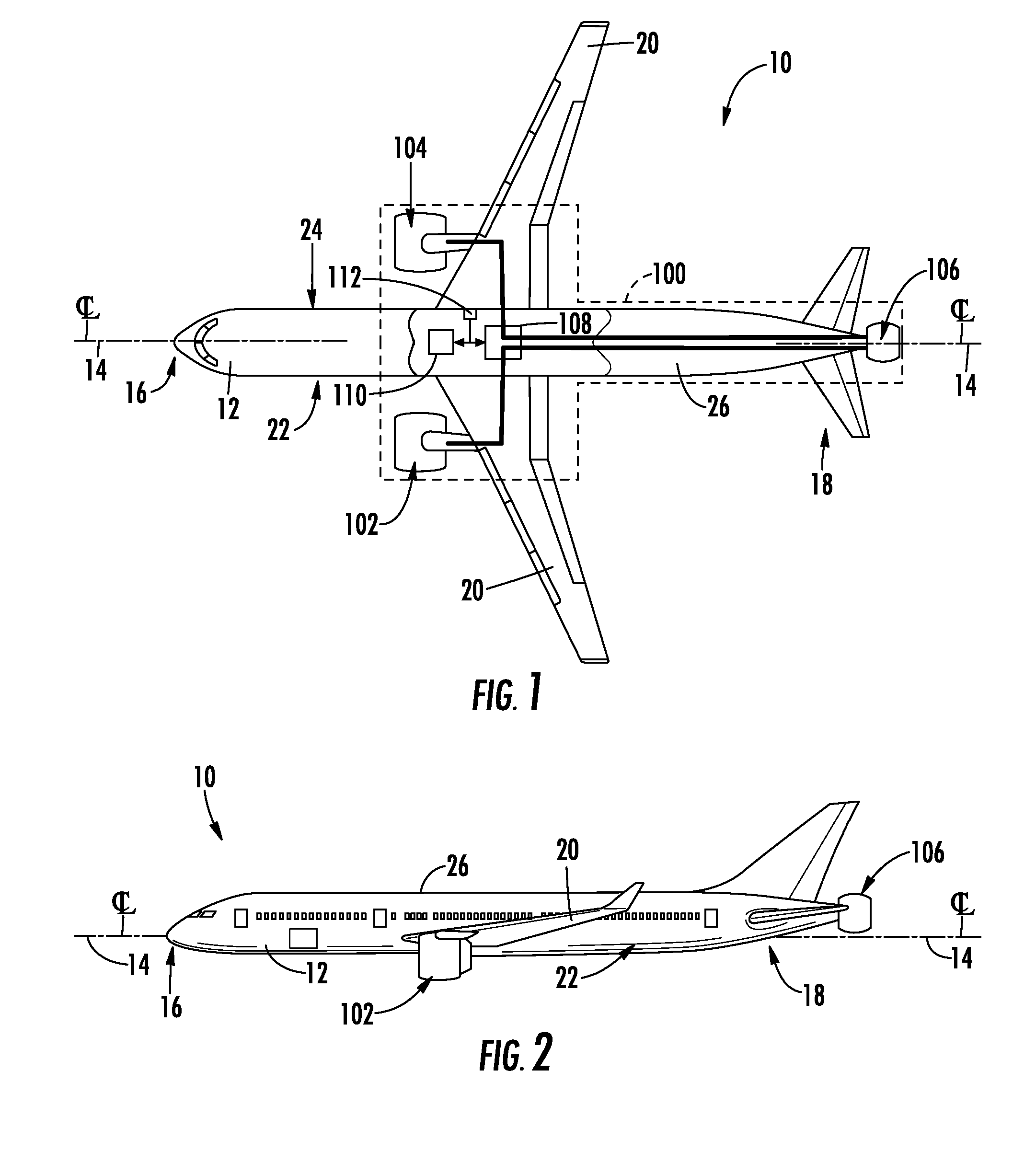
[0021]In general, the present subject matter is directed to a gas-electric propulsion system for an aircraft such as but not limited to ...


PUM


Abstract

In one aspect the present subject matter is directed to a gas-electric propulsion system for an aircraft. The system may include a turbofan jet engine, an electric powered boundary layer ingestion fan that is coupled to a fuselage portion of the aircraft aft of the turbofan jet engine, and an electric generator that is electronically coupled to the turbofan jet engine and to the boundary layer ingestion fan. The electric generator converts rotational energy from the turbofan jet engine to electrical energy and provides at least a portion of the electrical energy to the boundary layer ingestion fan. In another aspect of the present subject matter, a method for propelling an aircraft via the gas-electric propulsion system is disclosed.

Description

CROSS-REFERENCE TO RELATED APPLICATIONS[0001]This non-provisional application claims the benefit of priority under 35 U.S.C. §119(e) to U.S. Provisional Patent Application No. 62 / 107,196, entitled “GAS-ELECTRIC PROPULSION SYSTEM FOR AN AIRCRAFT”, filed Jan. 23, 2015, which is herein incorporated in its entirety by reference.FIELD OF THE INVENTION[0002]The present subject matter relates generally to a gas-electric propulsion system for an aircraft. More particularly, the present subject matter relates to a gas-electric propulsion system that converts rotational energy from a gas powered aircraft engine into electric energy via a low pressure (LP) and / or a high pressure (HP) electric generator to drive an electric powered boundary layer ingestion fan.BACKGROUND OF THE INVENTION[0003]A conventional commercial aircraft has a fuselage (tube) and wing configuration, and a propulsion system that provides thrust. The propulsion system generally includes two or more jet engines such as turbo...

Claims


Application Information

Patent Timeline
IPC IPC(8): B64D27/24B64D27/18
CPCB64D27/24B64D27/18Y10S903/906B64D2027/026B64D2205/00Y10S903/905Y10S903/907B64D27/02B64D27/20Y02T50/60Y02T50/10B64C21/01B64C21/06
Inventor HAMEL, JEFFREY ANTHONYMURROW, KURT DAVID
Owner GENERAL ELECTRIC CO
Why Eureka
Try Eureka