Wheelchair

a technology for wheelchairs and wheelchairs, applied in wheelchairs/patient conveyances, medical transportation, ambulance services, etc., can solve the problems of inconvenient user standing alone, and achieve the effect of preventing unstableness

Active Publication Date: 2016-08-04
FRANCE BED
View PDF5 Cites 13 Cited by
  • Summary
  • Abstract
  • Description
  • Claims
  • Application Information

AI Technical Summary

Benefits of technology

[0019]According to the present invention, when the user stands up and the seat rises, the wheel is automatically braked in interlock with the rising motion of the seat. Therefore, the user can be prevented from becoming unstable by a movement of the wheelchair made when the user stands up.
[0020]FIG. 1 is a front view of a wheelchair according to a first embodiment of the present invention.
[0021]FIG. 2 is a side view of the wheelchair in a state in which brake mechanisms are released while a seat is lowered.
[0022]FIG. 3 is an enlarged view of the brake mechanisms of the wheelchair in the state shown in FIG. 2.
[0023]FIG. 4 is a cross-sectional view of a height adjustment mechanism for adjusting a height position of a footrest.
[0024]FIG. 5 is a side view of the wheelchair in a state in which the brake mechanisms work while the seat is raised.

Problems solved by technology

In the case of wheelchairs, which are often used by users unable to use their legs, feet, and waists properly, such as the elderly, it is inconvenient that the users cannot stand by themselves from a state in which they sit in the wheelchairs, unless they receive assistance from helpers.

Method used


Image

  • Wheelchair
  • Wheelchair
  • Wheelchair

Examples


first embodiment

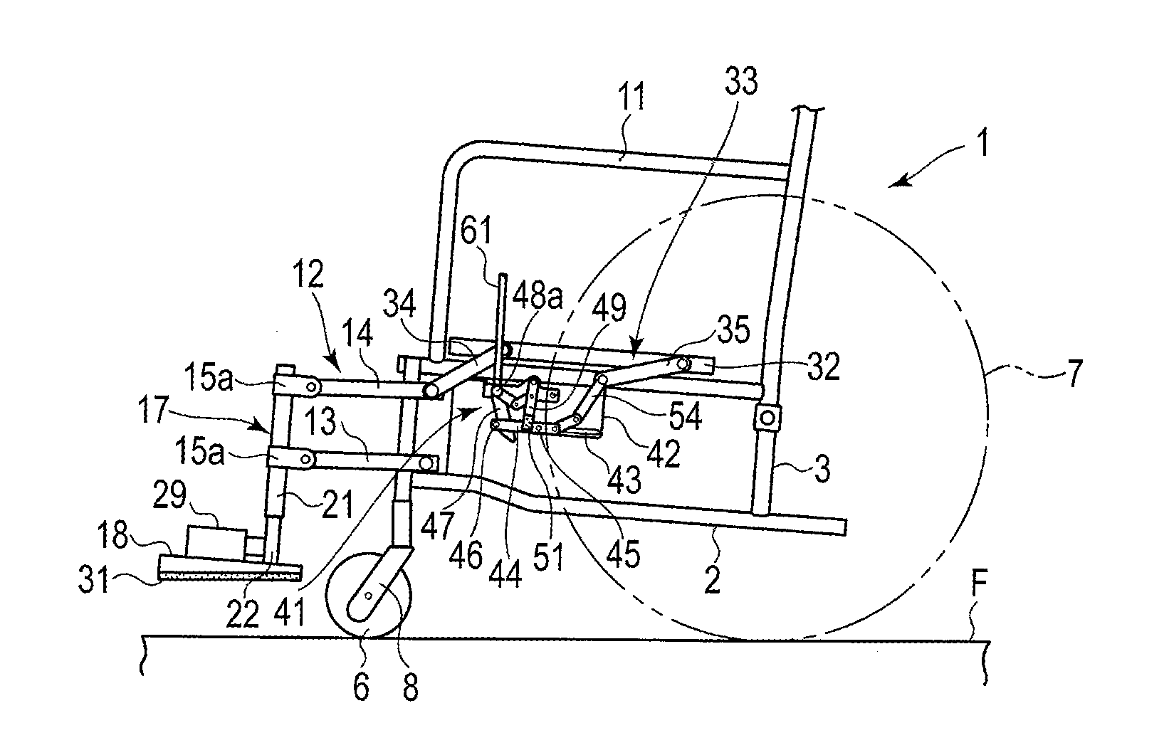
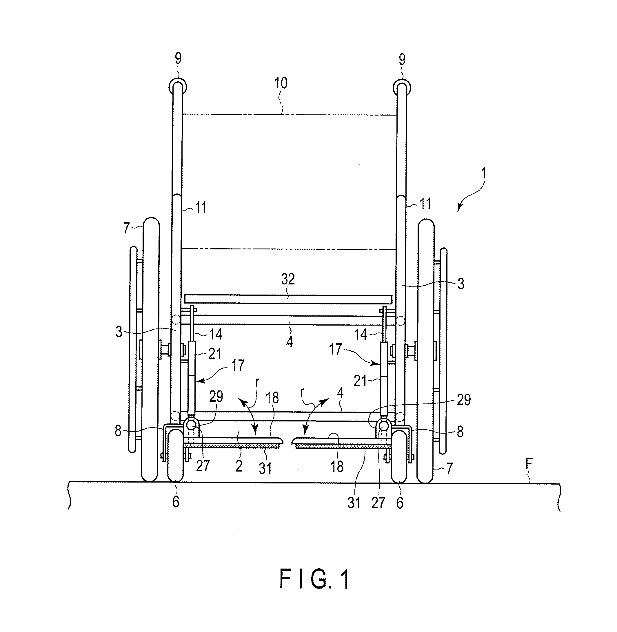
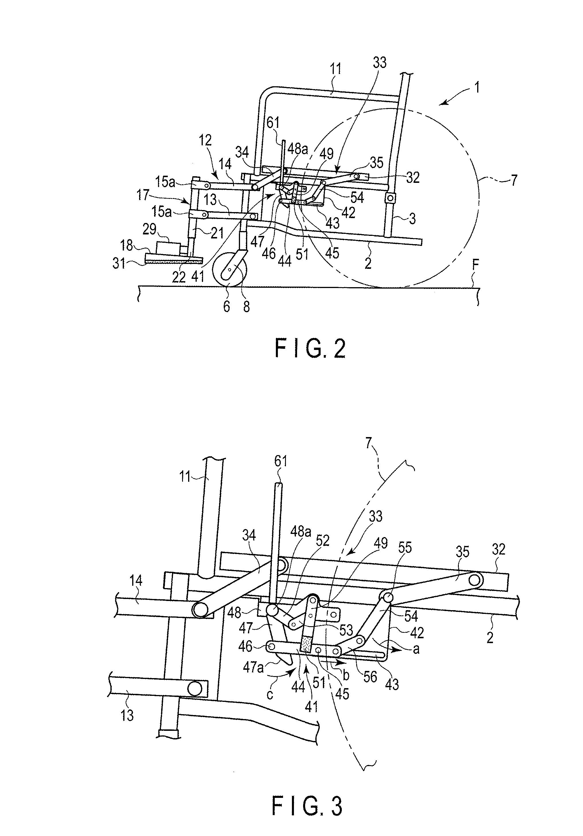
[0035]FIG. 1 to FIG. 9 show a first embodiment of the present invention. FIG. 1 is a front view of a wheelchair 1, and FIG. 2 is a side view thereof. The wheelchair 1 comprises a body 2 as a main body. The body 2 is structured by coupling a pair of side frames 3 formed in the shape of a rectangular frame in parallel to keep a predetermined distance therebetween by transverse pipes 4.

[0036]It should be noted that the body 2 may has the structure in which the pair of side frames 3 are coupled to be foldable in a width direction by links instead of the transverse pipes 4. That is, the body 2 may be foldable flat in the width direction.

[0037]Front wheels 6 are provided at the lower parts of pipes at the front ends of the pair of side frames 3, and rear wheels 7 are provided at intermediate parts of pipes at the back ends. The front wheels 6 and the rear wheels 7 contact a floor F, which is a contact patch.

[0038]To the lower ends of the pipes at the front ends of the side frames 3, suppo...

second embodiment

[0115]FIG. 10 and FIG. 11 show a wheelchair 1B according to a second embodiment of the present invention. The present embodiment is a modification of the second link mechanism 33 of the first embodiment. The same portions as those of the first embodiment are given the same symbols, and explanations thereof are omitted.

[0116]The second link mechanism 33 of the present embodiment is composed of one interlock link 63, one end of which is coupled and fixed to the bottom surface on the front end side of the seat 32 at a predetermined angle of inclination. The other end of the interlock link 63 is integrally attached to one end of the second link 14 of the first link mechanism 12, which is pivotally attached to the upper part on the front end side of the body 2. That is, the interlock link 63 rotates integrally with the second link 14.

[0117]In the present embodiment, the interlock link 63 is formed separately from the second link 14; however, they may be integrated, that is, may be contin...

third embodiment

[0134]FIG. 12 to FIG. 14 show a third embodiment of the present invention. A wheelchair 1C of the third embodiment is a modification of the wheelchair 1 of the first embodiment. In the third embodiment, the same portions as those of the first embodiment are given the same symbols, and explanations thereof are omitted.

[0135]In the first embodiment, the footrests 18 are provided on the front end side of the body 2 to be movable up and down. However, in the third embodiment, footrests 18A are provided on the front end side of the body 2 to be not movable up and down, but are fixedly provided on the body 2.

[0136]To be specific, at the front ends of the pair of side frames 3 of the body 2, a pair of support members 71 (only one of which is shown in the figures) formed by bending pipe materials in a reverse L-shape is provided to project forward. In addition, the footrests 18A are attached to the lower ends of the support members 71.

[0137]On the top surfaces of the footrests 18A, coupling...


PUM


Abstract

There are provided a rear wheel rotatably provided in a body, a seat disposed on a top surface side of the body, a seat link mechanism by which the seat is supported to be movable up and down between a raised position and a lowered position on the top surface side of the body, and a brake mechanism which inhibits the rear wheel from rotating in interlock with the seat link mechanism, when the seat is raised from the lowered position to the raised position.

Description

CROSS REFERENCE TO RELATED APPLICATIONS[0001]This application is a Continuation Application of PCT Application No. PCT / JP2015 / 075470, filed Sep. 8, 2015 and based upon and claiming the benefit of priority from prior Japanese Patent Applications No. 2015-014960, filed Jan. 29, 2015; No. 2015-095407, filed May 8, 2015; and No. 2015-095408, filed May 8, 2015, the entire contents of all of which are incorporated herein by reference.BACKGROUND OF THE INVENTION[0002]1. Field of the Invention[0003]The present invention relates to a wheelchair having the function of assisting a sitting user in standing up.[0004]2. Description of the Related Art[0005]In the case of wheelchairs, which are often used by users unable to use their legs, feet, and waists properly, such as the elderly, it is inconvenient that the users cannot stand by themselves from a state in which they sit in the wheelchairs, unless they receive assistance from helpers. In addition, even if the users are assisted by the helpers...

Claims


Application Information

Patent Timeline
Patent Type & Authority Applications(United States)
IPC IPC(8): A61G5/10A61G5/02A61G5/14
CPCA61G5/1021A61G5/02A61G5/14A61G5/101A61G5/1018A61G5/1035A61G5/1059A61G5/1054A61G5/128
Inventor OOYAMA, KEI
Owner FRANCE BED
Why Eureka
Try Eureka