
Vehicle seat

a technology for vehicle seats and backrests, applied in the field of vehicle seats, can solve the problems of limiting the degree of freedom in the design of vehicle seats, difficult to precisely regulate the rotation of link members, and difficult to arrange other mechanisms or reduce the size of seats, etc., and achieve the effect of convenient fixation

Active Publication Date: 2016-08-04
TS TECH CO LTD
View PDF2 Cites 14 Cited by
  • Summary
  • Abstract
  • Description
  • Claims
  • Application Information

AI Technical Summary

Benefits of technology

The patent text is discussing the need for a vehicle seat that can support an occupant during cornering and reduce impact in a rear-end collision. However, this requires a mechanism for changing the orientation of a part of the seat back and a mechanism for allowing a rearward movement of the pressure-receiving member. This results in a seat that takes up a lot of space, making it difficult to design other mechanisms or reduce the size of the seat. The technical effect of the patent is to provide a solution that allows for both functions without taking up too much space in the seat design.

Problems solved by technology

These mechanisms may disadvantageously occupy a large space within the seat back, which makes it difficult to arrange other mechanisms or to reduce the size of the seat; as a result, there is a possibility to limit the degree of freedom in the design of the vehicle seat.
In the conventional art, it is difficult to precisely regulate the amount of rotation of the link member because the amount of rotation of the link member (inclination of the back plate) is regulated by controlling actuation and stoppage of the driving source.

Method used


Image

  • Vehicle seat
  • Vehicle seat
  • Vehicle seat

Examples


Embodiment Construction

[0077]One embodiment of the present invention will be described in detail with reference made to the drawings, where necessary.

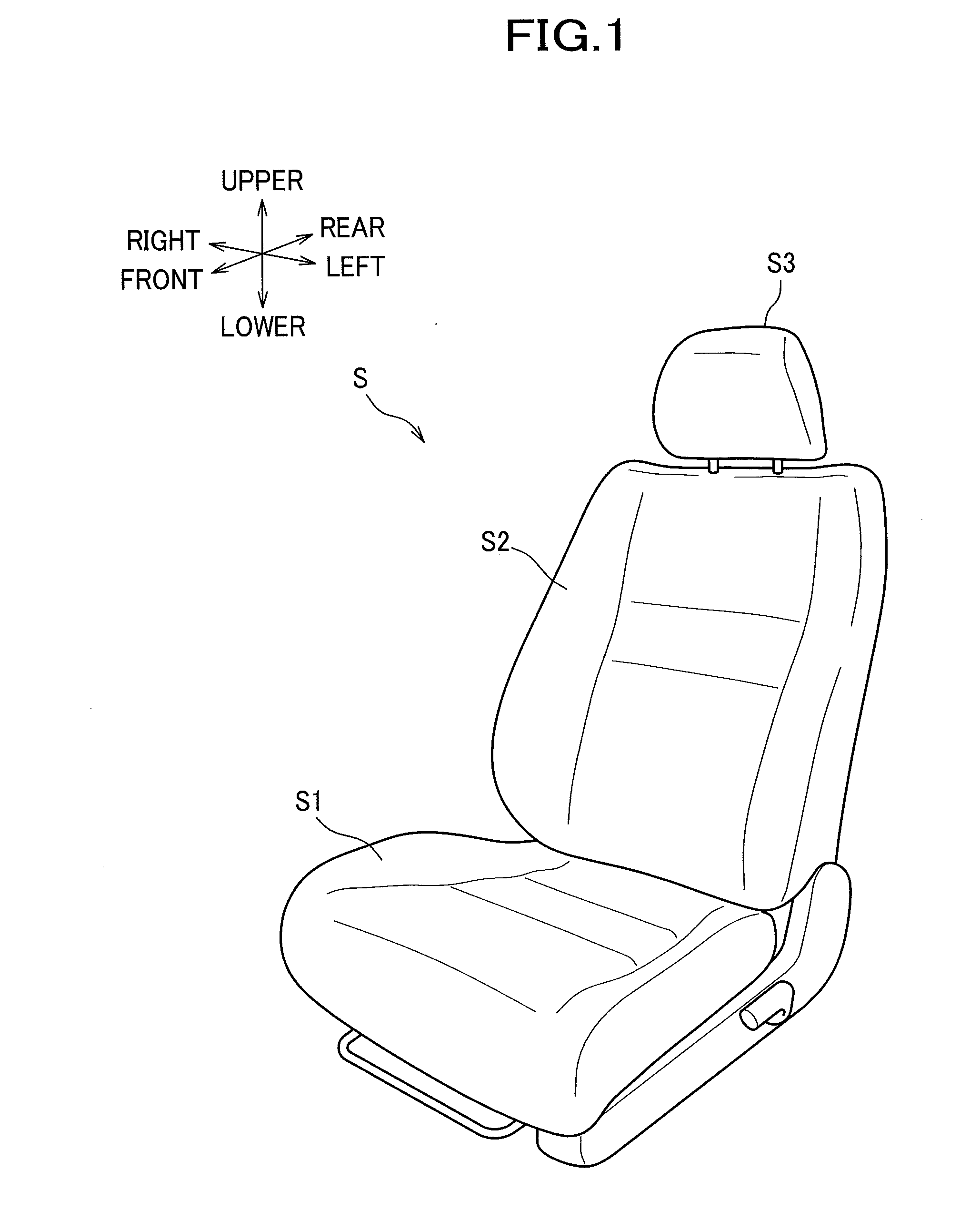
[0078]As seen in FIG. 1, a vehicle seat according to this embodiment is configured as a car seat S used for a driver's seat and the like of an automobile, and mainly includes a seat cushion S1, a seat back S2, and a headrest S3.

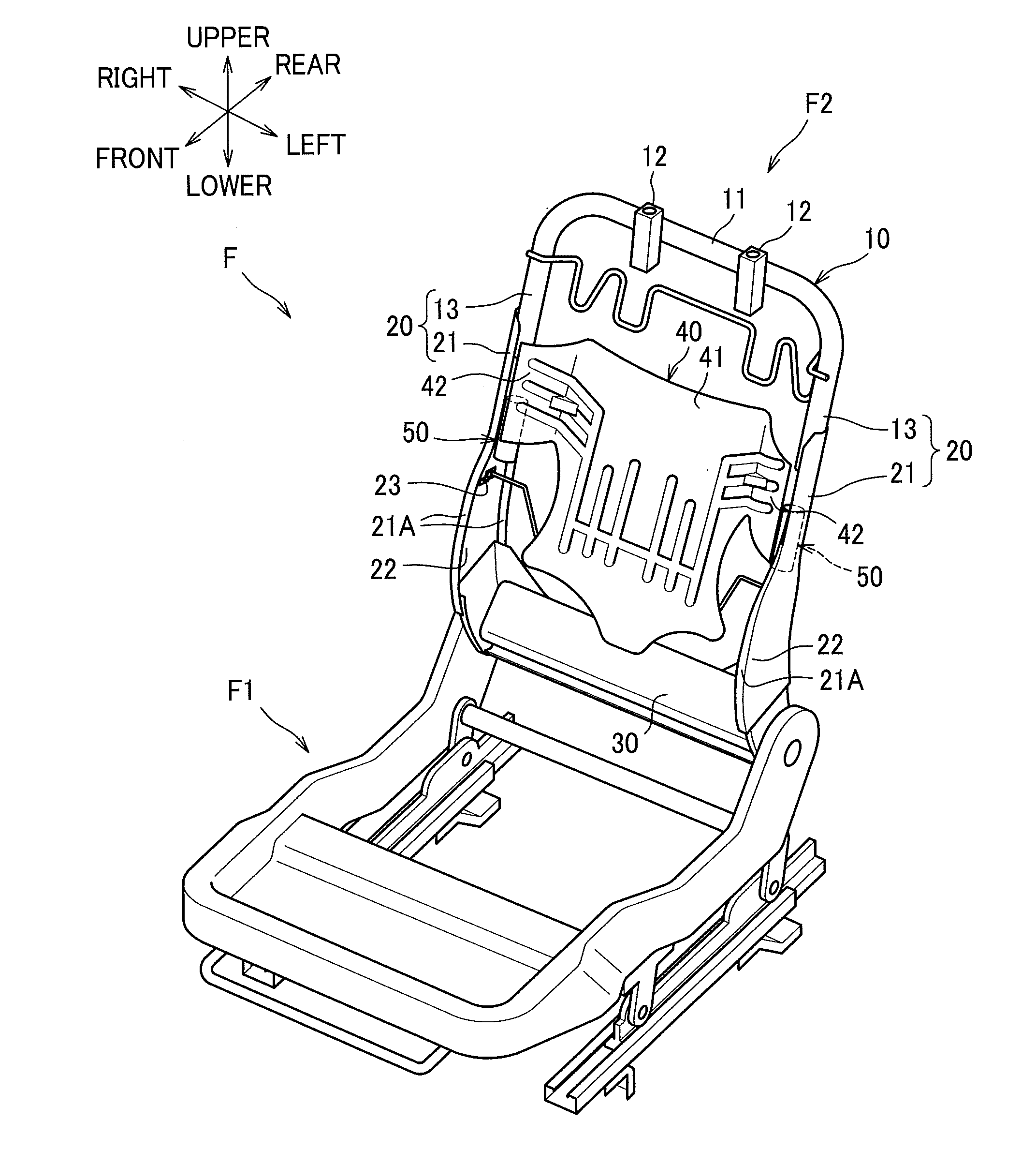
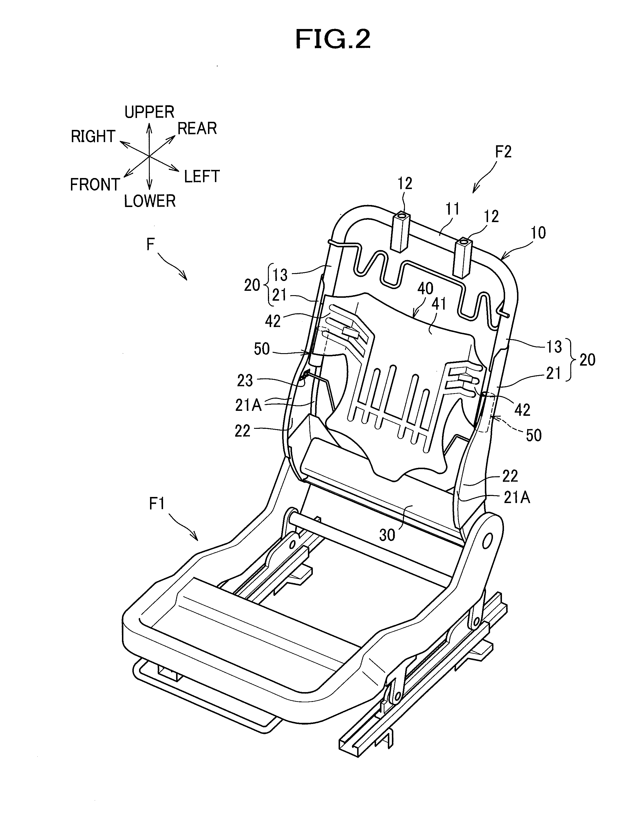
[0079]A seat frame F shown in FIG. 2 as an example of a frame is embedded in the seat cushion S1 and the seat back S2. The seat frame F mainly includes a seat cushion frame F1 constituting a frame of the seat cushion S1, and a seat back frame F2 constituting a frame of the seat back S2. The seat cushion S1 is configured such that the seat cushion frame F1 is covered with a cushion material made of urethane foam or the like, and an outer skin material made of synthetic leather or fabric. The seat back S2 is configured such that the seat back frame F2 is covered with a seat back pad BP made of a cushion material such as urethane foam (s...


PUM


Abstract

The object of the invention is to provide a vehicle seat which can improve degree of freedom in the design of the vehicle seat. A vehicle seat with a seat cushion and a seat back includes: right and left side frames 20 constituting right and left frames of the seat back; a pressure-receiving member 40 disposed between the right and left side frames 20 and configured to receive a load from an occupant; and a driving mechanism 50 disposed at each of right and left sides of the pressure-receiving member 40 and configured to cause a right end portion or a left end portion of the pressure-receiving member 40 to move from an initial position to an advanced position that is located frontward of the initial position or to move from the advanced position to the initial position, wherein the driving mechanism 50 includes a linkage (drive link member 100 and contact link member 200) configured to be connected to the pressure-receiving member 40 and a driving source 52 configured to actuate the linkage, and wherein the linkage is configured to operate when a load equal to or greater than a predetermined amount is input from the occupant to the pressure-receiving member 40 to cause the pressure-receiving member 40 to move to a backward position that is located rearward of the initial position.

Description

TECHNICAL FIELD[0001]The present invention relates to a vehicle seat with a seat cushion and a seat back.BACKGROUND ART[0002]Conventionally, there is known a vehicle seat for a car and the like, in which a part of a seat back is oriented to a turning direction so that a centrifugal force applied to an occupant during cornering is appropriately supported by the seat back (see patent Documents 1-3).[0003]For example, a seat described in Patent Document 1 comprises right and left side frames of a seat back, a long link member disposed between the right and left side frames and configured to support an occupant through a movable cushion, and a short link member rotatably provided at each side frame and connected to each side of the long link member, wherein the orientation of the movable cushion is changed by actuating the link.[0004]A seat device described in Patent Document 2 comprises a back plate disposed between right and left side frames of a seat back and having swingable end por...

Claims


Application Information

Patent Timeline
IPC IPC(8): B60N2/42B60N2/64B60N2/22
CPCB60N2/686B60N2/72B60N2/2222B60N2/64B60N2/42745B60N2/22B60N2/4228B60N2002/022B60N2/667B60N2/026
Inventor SUGIYAMA, SHINJI
Owner TS TECH CO LTD
Learn More