Counterweight Device for Arranging Accumulators Inside the Counterweight of a Working Machine

Inactive Publication Date: 2016-08-04
KEJTERPILLAR R L
View PDF0 Cites 5 Cited by
  • Summary
  • Abstract
  • Description
  • Claims
  • Application Information

AI Technical Summary

Benefits of technology

[0017]According to the invention described in claim 1, in the working machine in which the accumulators are arranged inside the counterweight, the accumulators can be set at the machine body side in the temporary placement support structure even in a counterweight not-yet-installed state, that is, prior to the installation of the counterweight onto the machine body. Therefore, the machine body can be moved by connecting the piping at the machine body side to accumulators. Further, when detachment of the counterweight is necessary due to the maintenance or the like of the machine body, only the counterweight can be detached without detaching the piping, in the state where the piping at the machine body side is connected to the accumulators in the temporary placement support structure. Further, by arranging the accumulators inside the counterweight, the counterweight filling quantity corresponding to the accumulator weight can be reduced. Because the total weight of the counterweight remains unchanged, reinforcement of the peripheral structure of the accumulator-fitted portion at the machine body side becomes unnecessary. In addition, because the accumulators are arranged inside the counterweight, layout of the machine body side becomes advantageous.
[0018]According to the invention described in claim 2, the temporary placement support structure temporarily joint the accumulator support frame unit that can be arranged inside the counterweight, in the state where the accumulator support frame unit accommoda

Problems solved by technology

However, when the accumulators have been fitted inside the counterweight like the working machine in Patent Document 1, or when the accumulators have been fitted to the upper surface of the counterweight or inside the counterweight like the working machine in Patent Document 2, it is diff

Method used


Image

  • Counterweight Device for Arranging Accumulators Inside the Counterweight of a Working Machine
  • Counterweight Device for Arranging Accumulators Inside the Counterweight of a Working Machine
  • Counterweight Device for Arranging Accumulators Inside the Counterweight of a Working Machine

Examples


Example

[0030]Hereinafter, a first embodiment and a second embodiment of the present invention will be described in detail with reference to FIGS. 1 to 7 and FIGS. 8 and 9, respectively.

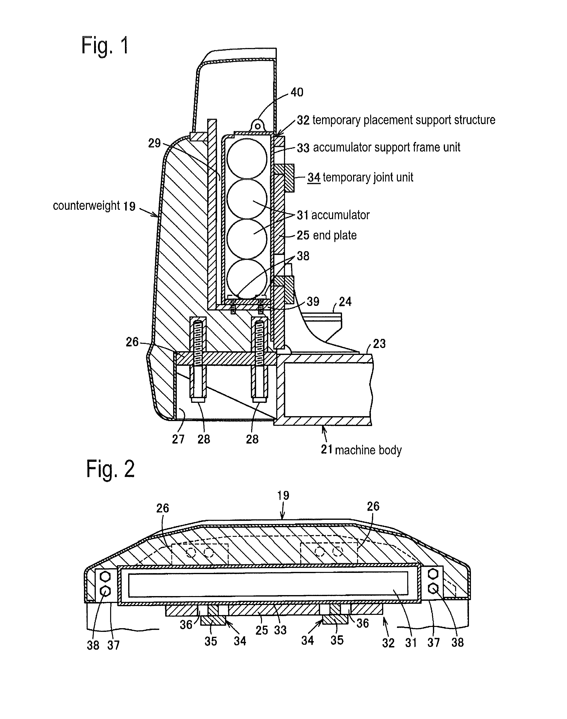
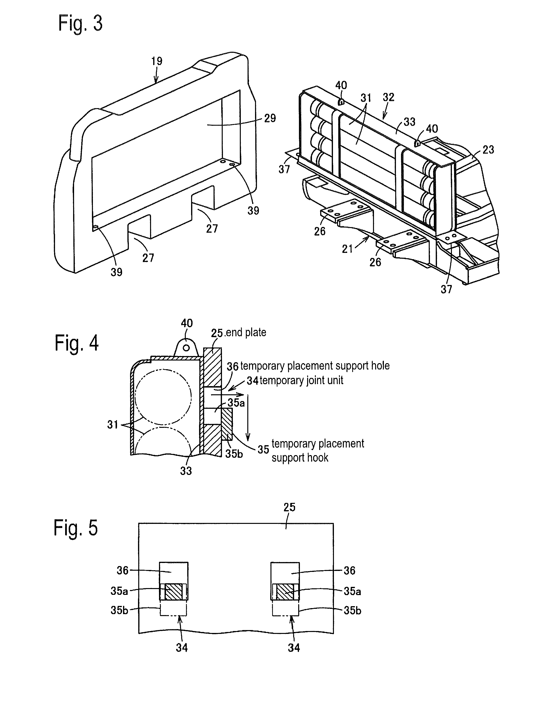
[0031]First, the first embodiment will be described with reference to FIGS. 1 to 7.

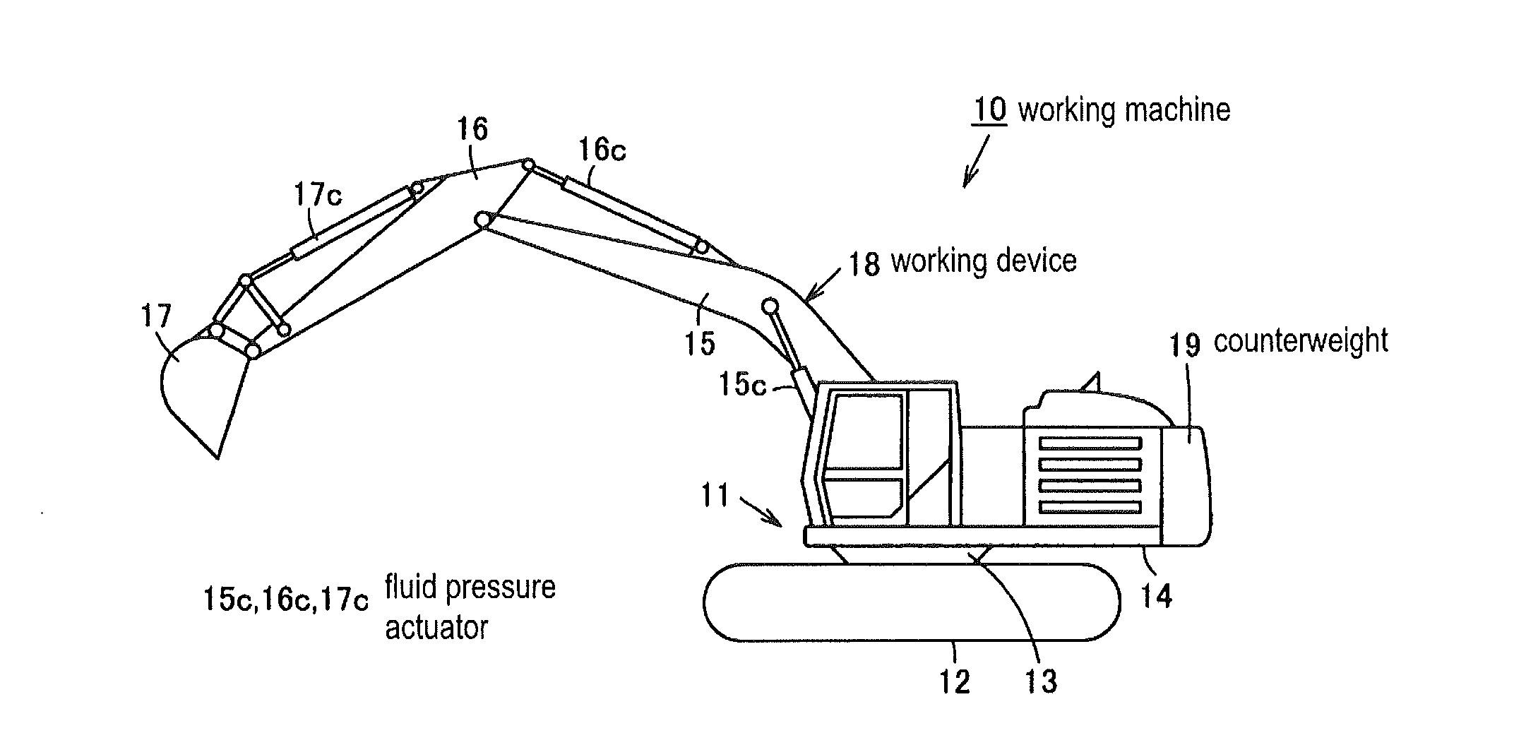
[0032]As shown in FIG. 6, a hydraulic shovel 10 as a working machine includes as a machine body 11, a crawler type lower traveling body 12 that is driven to travel by a traveling motor (not shown), and an upper slewing body 14 that is driven to slew by a slewing motor (not shown) via a slewing bearing unit 13 on the lower traveling body 12. At the front side of the upper slewing body 14, there is mounted a working device 18 that includes a boom 15 which is turned by a boom cylinder 15c, a stick 16 which is turned by a stick cylinder 16c, and a bucket 17 which is turned by a bucket cylinder 17c. At the rear side of the upper slewing body 14, there is mounted a counterweight 19 for keeping weight balance with the working device ...

Example

[0056]Next, a second embodiment will be described with reference to FIGS. 8 and 9. Portions similar to those in the first embodiment shown in FIGS. 1 to 7 are attached with identical reference numerals and their descriptions will be omitted.

[0057]In the second embodiment, a plate-shaped temporary placement jig 41 is prepared as a temporary placement exclusive jig separately from an end plate 25A of the slewing frame 21, and is fitted to the end plate 25A at the assembling time.

[0058]That is, a temporary placement support structure 32A shown in FIG. 8 includes the temporary placement jig 41 that extends the end plate 25A to a height at which the end plate 25A can match the accumulator support frame unit 33, an upper end of the end plate 25A being positioned at a low portion of the accumulator support frame unit 33 at the slewing frame 21 side adjacent to the counterweight 19.

[0059]The temporary placement jig 41 has a plate part 44 which is fitted to an upper edge part of the end plat...


PUM


Abstract

Counterweight device in which an accumulator is disposed inside a counterweight, the work machine connecting the accumulator to piping at the machine body side and capable of moving a machine body or work device even though the counterweight is not attached to the body. A counterweight is fixed to a mount base at the rear end part of a swinging frame, an accumulator installed inside the counterweight by means of a temporary placing support structure. The temporary placing support structure can be temporarily placed on and attached to the end plate at the swinging frame side before attaching the counterweight.

Description

TECHNICAL FIELD[0001]The present invention relates to a counterweight device in a working machine that has accumulators arranged inside a counterweight.BACKGROUND ART[0002]In recent years, there have been developed hydraulic shovels that accumulate in accumulators positional energy of a working unit and that enable the accumulated positional energy to be reused for a lift operation and the like of a working machine. In this case, in order to accumulate sufficient positional energy, a plurality of accumulators having large capacities need to be installed. Further, an accumulator arrangement space needs to be secured on a hydraulic shovel slewing frame, and a structure (the slewing frame) design that can bear the weight of the accumulators is demanded.[0003]On the other hand, because of the structure of the hydraulic shovel, heavy goods are desired to be arranged at the back of the vehicle. Therefore, at present, there is employed a design for providing the accumulator arrangement spa...

Claims


Application Information

Patent Timeline
IPC IPC(8): E02F9/22E02F9/18
CPCE02F9/18E02F9/2271E02F9/2264E02F9/2217
Inventor KOHZU, YOSHIHISANAKAI, AKITO
Owner KEJTERPILLAR R L
Why Eureka
Try Eureka