LED lamp

a technology of led lamps and lampshades, which is applied in the field of lighting, can solve the problems of difficulty in providing specific heat dissipation for heating sources, low heat dissipation efficiency, and inability to solve the disadvantages of prior art solutions, and achieve the effects of high heat dissipation efficiency, long life for use, and dissipation of hea

Inactive Publication Date: 2016-08-04
ZOU XIAOFENG +5
View PDF3 Cites 19 Cited by
  • Summary
  • Abstract
  • Description
  • Claims
  • Application Information

AI Technical Summary

Benefits of technology

[0029]The solution of the present invention can specifically dissipate heat generated by the heating elements in the LED lamp, and has advantages of high efficiency of heat dissipation, long life for use, low noise, dust resistance and the like. The LED lamp can resist lashing and vibrating, has a simple structure, and can be maintained easily. Moreover, when the LED lamp of the present invention is used, the pre-mounted nut on the screw is slacked and unloaded. Then, the screw extends through the fixed hole of the second bracket on which the lamp is mounted and fixed, and the nut is mounted on the screw. Further, the screw is regarded as an axis and the emitting light direction of the lamp on the second bracket is adjusted according to the axis, and the second bracket is locked on the first bracket by tightening the nut. The LED lamp can be mounted stably without risk of an electric shock while well controlling the angle of radiating light.

Problems solved by technology

However, the issues related to heat dissipation are important factors for limiting its development.
However, both such manners have disadvantages of a lower efficiency of heat dissipation, difficulty providing specific heat dissipation for the heating source.
In other words, the solutions in prior art cannot solve these disadvantages.
When the above is used, there are a number of issues: 1. the base may shake, and the lamp may not be mounted stably; 2. when the power supply is turned on, the base is charged, resulting in safety problems for operators; 3. When the lamp holder and the lamp cradle is assembled, the lamp holder is twisted and then connected to the lamp cradle.
However, when the lamp holder is twisted to the end, the radiating angle of the lamp is generally not best, and then it needs to be adjusted, resulting in inconvenient mounting of the lamp.

Method used


Image

  • LED lamp
  • LED lamp
  • LED lamp

Examples


first embodiment

[0079]For facilitating mounting the heat sink module on the housing, a connecting component is also provided. Referring to FIGS. 14 to 16, in a first embodiment, the connecting component includes a mounting plate 30, the base plate 10 is fastened to the mounting plate 30, a plurality of first brackets 31 are evenly provided along the periphery of the mounting plate 30 and the length of the first brackets 31 can be adjusted.

[0080]The mounting plate 30 can be of a rectangle shape, a long circle shape and the like according to actual uses for adapting to the above different embodiments.

[0081]The first brackets 31 are of a thin sheet shape on which a plurality of depressions 310 perpendicular to the length of the first brackets 31 are evenly provided, and the depressions 310 can reduce strength which the bracket can bear. When it needs to adjust the length of the first brackets 31, an external force can be applied to the respective depressions, for breaking the first brackets 31 and ena...

second embodiment

[0082]Referring to FIGS. 17 to 19, in a second embodiment, the connecting component includes a mounting plate 30, the base plate 10 is fastened to the mounting plate 30, and a plurality of second brackets 32 are evenly provided along the periphery of the mounting plate 30. The connecting component further includes a plurality of third brackets which can slide along a length of the second brackets, a groove is provided on the second brackets and the third brackets, and fasteners pass through the groove. After the relative position between the second brackets and the third brackets is adjusted, the third brackets 33 can be fastened to the second brackets 32. Preferably, fasteners are wing screws.

third embodiment

[0083]Referring to FIGS. 20 to 22, in a third embodiment, the connecting component comprises a fourth bracket 34 fastened to the base plate 10 and a fifth bracket 35 mounted on the fourth bracket 34. Preferably, a hole is provided on the fourth bracket 34, and a plurality of holes and / or grooves are provided on the fifth bracket 35 along a length of the fifth bracket 35. The relative position between the fourth bracket 34 and the fifth bracket 35 can be adjusted by coordination of different holes and / or grooves on the fifth bracket 35 and the hole on the fourth bracket 34.

[0084]A nut and a screw hole are provided on the fifth bracket 35, and can be configured to fix the lamp holder.

[0085]Referring to FIG. 23, in fourth embodiment, the difference from the third embodiment is that a cradle 50 and a clamp 60 are provided on the fifth bracket. The lamp holder can be placed in the cradle 50 and locked by the clamp 60, so that the lamp holder and the heat-dissipating structures are fasten...


PUM


Abstract

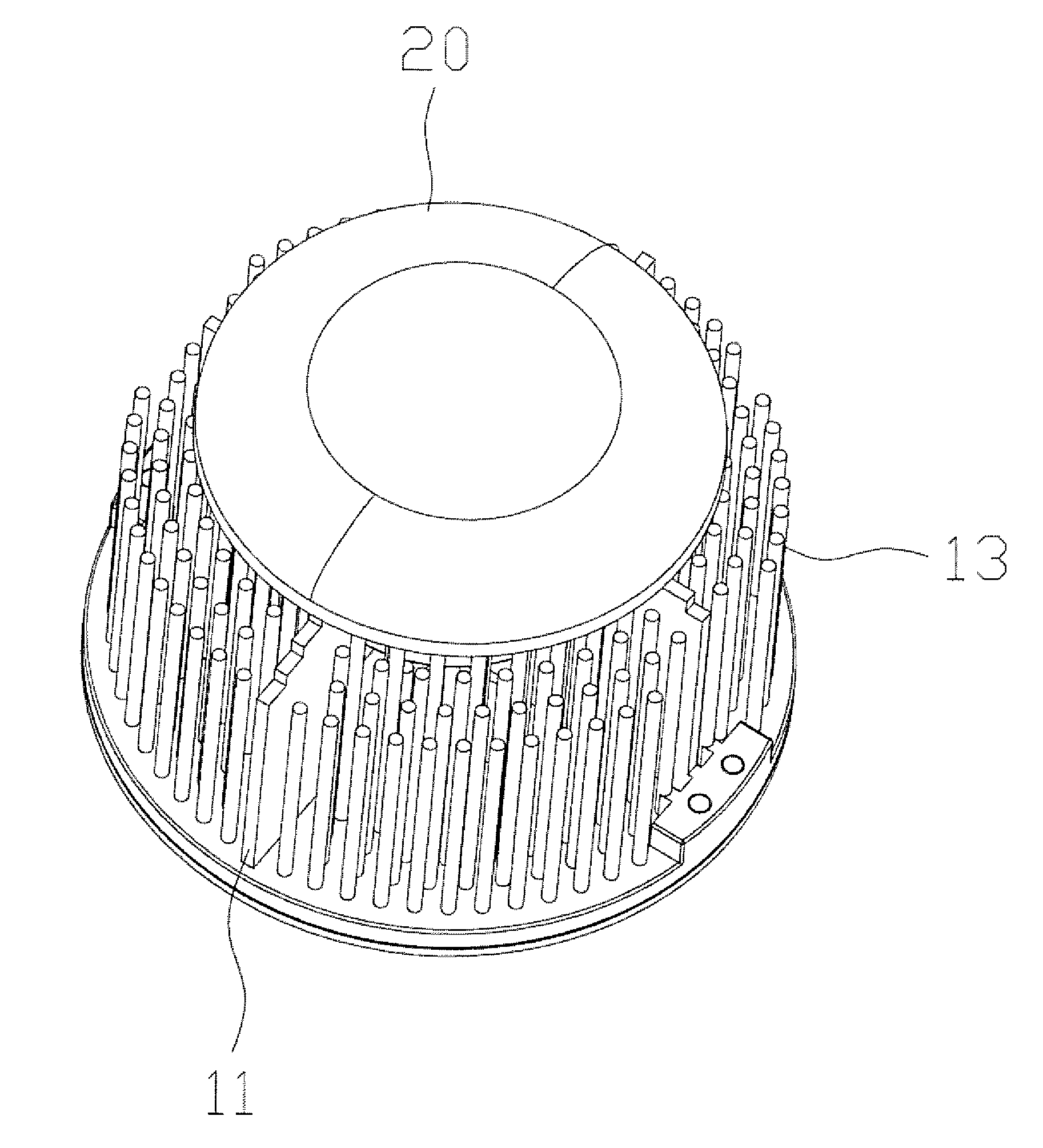
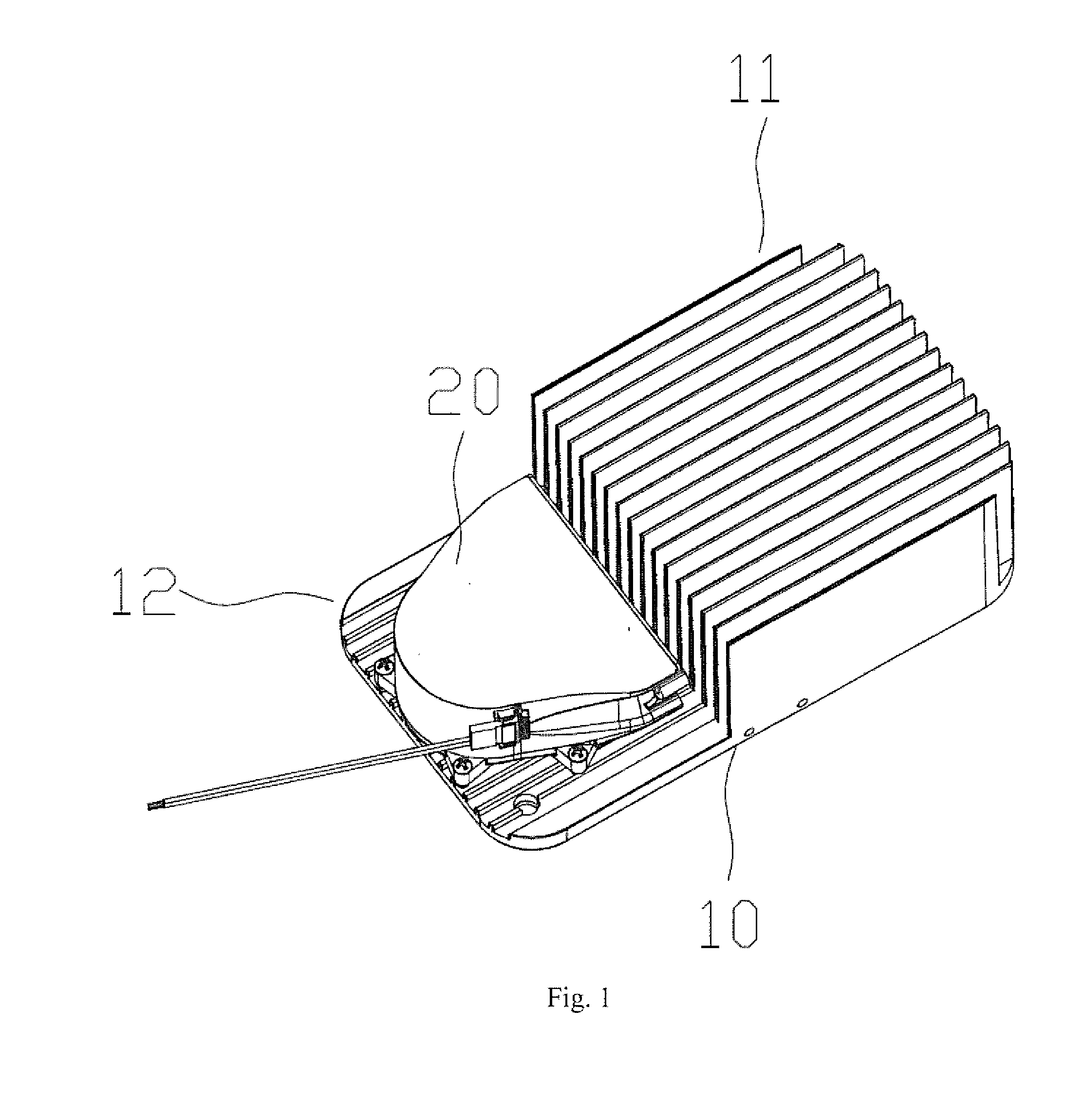
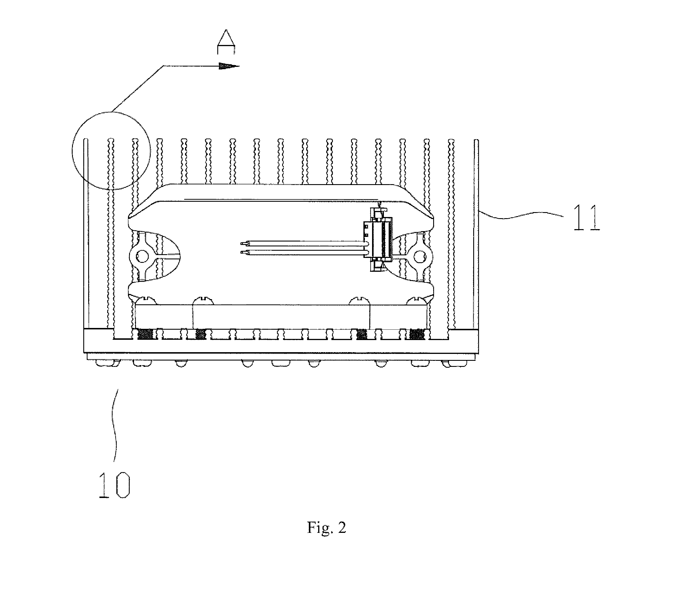
A LED lamp comprises a housing and a heat sink module provided on the housing and comprising a base plate, wherein one side of the base plate is provided with a heat-dissipating plane and the other side thereof is provided with a plurality of heat-dissipating structures, an air passage is formed among the heat-dissipating structures; the heat sink module further comprises at least a power device, an air outlet of the power device is aligned with the air passage. A LED lamp comprises a bracket and a lamp provided on the bracket; the bracket comprises a first bracket and a second bracket; the second bracket comprises a connecting portion and a connecting arm extending from both ends of the connecting portion to a same side thereof; the lamp is mounted on the connecting arm, a screw is provided on the first bracket, a fixed hole is provided on the connecting portion of the second bracket, the screw extends through the fixed hole of the second bracket and is locked by a nut.

Description

FIELD OF THE INVENTION[0001]The present disclosure relates to a lighting field, and more particularly relates to a LED lamp.BACKGROUND OF THE INVENTION[0002]As the technical development, the LED lamp is increasingly popular due to its advantages of high luminous efficiency, less power consumption, long life and the like. However, the issues related to heat dissipation are important factors for limiting its development. In prior art, the air passage are provided to dissipate heat generated by the power supply, circuit board and other heating elements, or heat exchange with the external is implemented by the lamp body. However, both such manners have disadvantages of a lower efficiency of heat dissipation, difficulty providing specific heat dissipation for the heating source. In other words, the solutions in prior art cannot solve these disadvantages.[0003]Currently, in the lighting industrial, the lamp is always provided with a lamp holder and a base for enabling the lamp to fix in t...

Claims


Application Information

Patent Timeline
Patent Type & Authority Applications(United States)
IPC IPC(8): F21V29/74F21V29/80F21V29/60
CPCF21V29/74F21Y2101/02F21V29/80F21V29/60F21V29/67F21V29/763F21V29/773F21Y2115/10
Inventor ZOU, XIAOFENGLI, QIANGLIU, YERENLIN, ZHIJINMO, KAIFAZHOU, RENGUI
Owner ZOU XIAOFENG
Why Eureka
Try Eureka