
Rifle grenade using bullet trap

a bullet trap and rifle grenade technology, applied in the direction of ammunition projectiles, weapons, transportation and packaging, etc., can solve the problems of inconvenient replacement, immediate fire back of enemy personnel, and unnecessary additional time, so as to increase the impact range and the effect of effective rang

Active Publication Date: 2016-08-04
HANWHA AEROSPACE CO LTD
View PDF2 Cites 4 Cited by
  • Summary
  • Abstract
  • Description
  • Claims
  • Application Information

AI Technical Summary

Benefits of technology

This invention is a range-increasing grenade for a rifle. It uses a bullet trap to absorb impacts and prevent damage to objects mounted in it, such as a robot or explosive. The grenade also allows for control of the robot using an external controller and can quickly strike enemy personnel or lines.

Problems solved by technology

This replacement is inconvenient, and requires an unnecessary additional time, so that it is impossible to immediately fire back enemy personnel, and thus to maintain fighting agility.
In addition, there are risks in which, when a rifleman fires the rifle grenade without removing the ball cartridge by mistake, the rifle grenade is detonated in front of the muzzle.
For this reason, there is a risk of surrounding personnel being injured.
However, such a weapon has problems in that, due to an additional percussion lock, an additional manufacturing cost is required, and weight thereof is increased to impose restrictions on carrying and handling.
In particular, since the weapon is given only to some limited specific members, firepower support is also limited.
On the other hand, the rifle that is a basic weapon which the rifleman carries is burdensome to the rifleman due to its weight.
Such a burden makes it inconvenient to carry and handle the rifle.
However, since a structural change of the rifle requires an enormous cost, a structural change is not economical.
In addition, even when the rifle is improved by such a structural change, the conventional problems cannot be completely removed.

Method used


Image

  • Rifle grenade using bullet trap
  • Rifle grenade using bullet trap
  • Rifle grenade using bullet trap

Examples


Embodiment Construction

[0055]The present invention will be described below in detail with reference to the appended drawings.

[0056]Here, the repeated description and the detailed description of the known function and configuration that would make a description of the gist of the present invention unnecessarily obscure will be omitted.

[0057]Embodiments of the present invention are provided to more completely describe the present invention to a person with ordinary skill in the art.

[0058]Shapes and sizes of components in the drawings may be modified for clearer description.

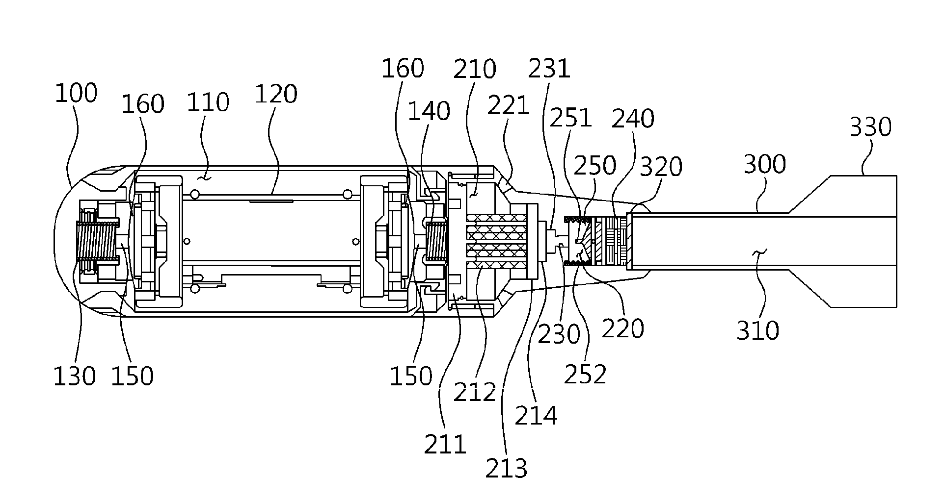
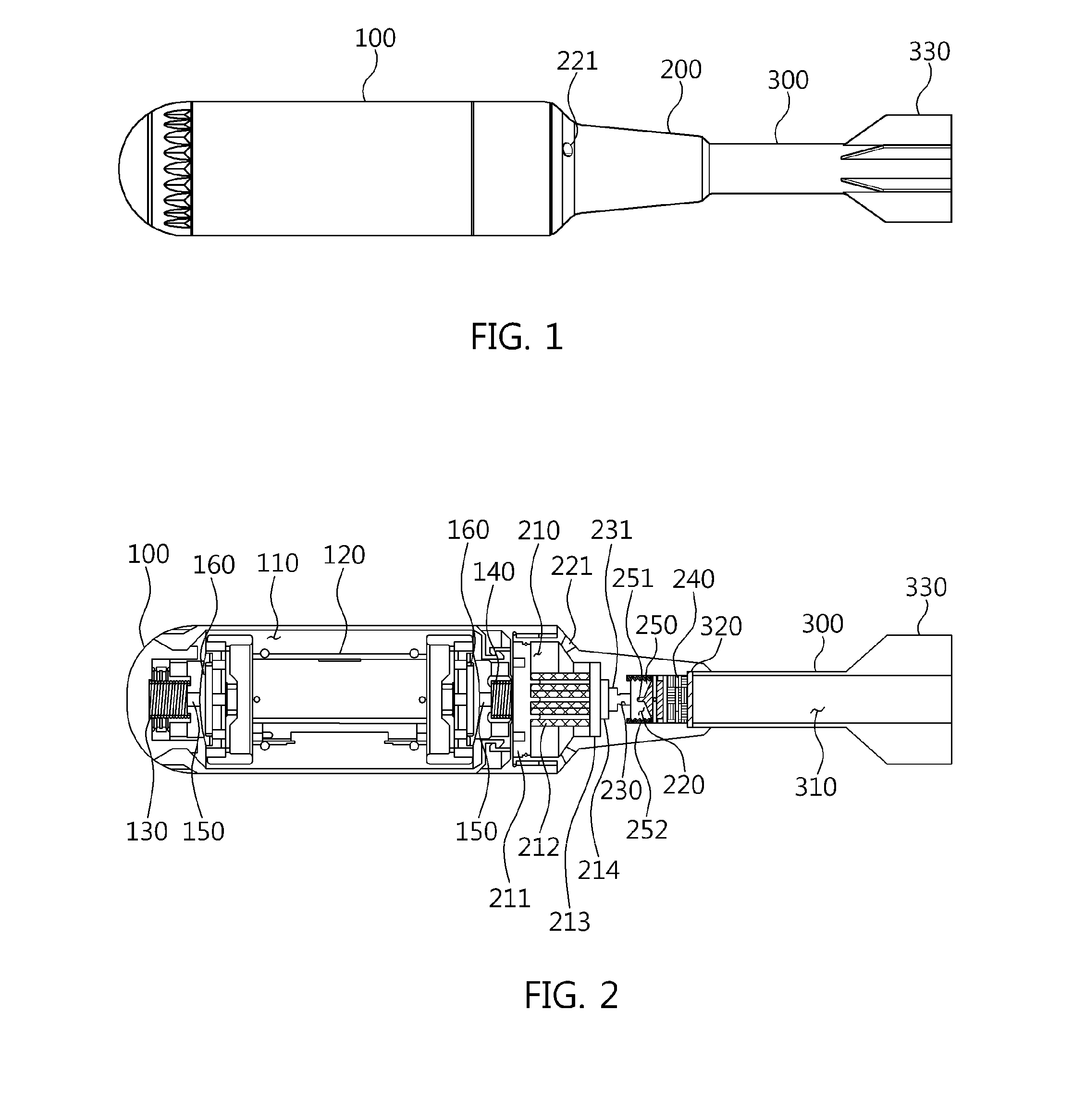
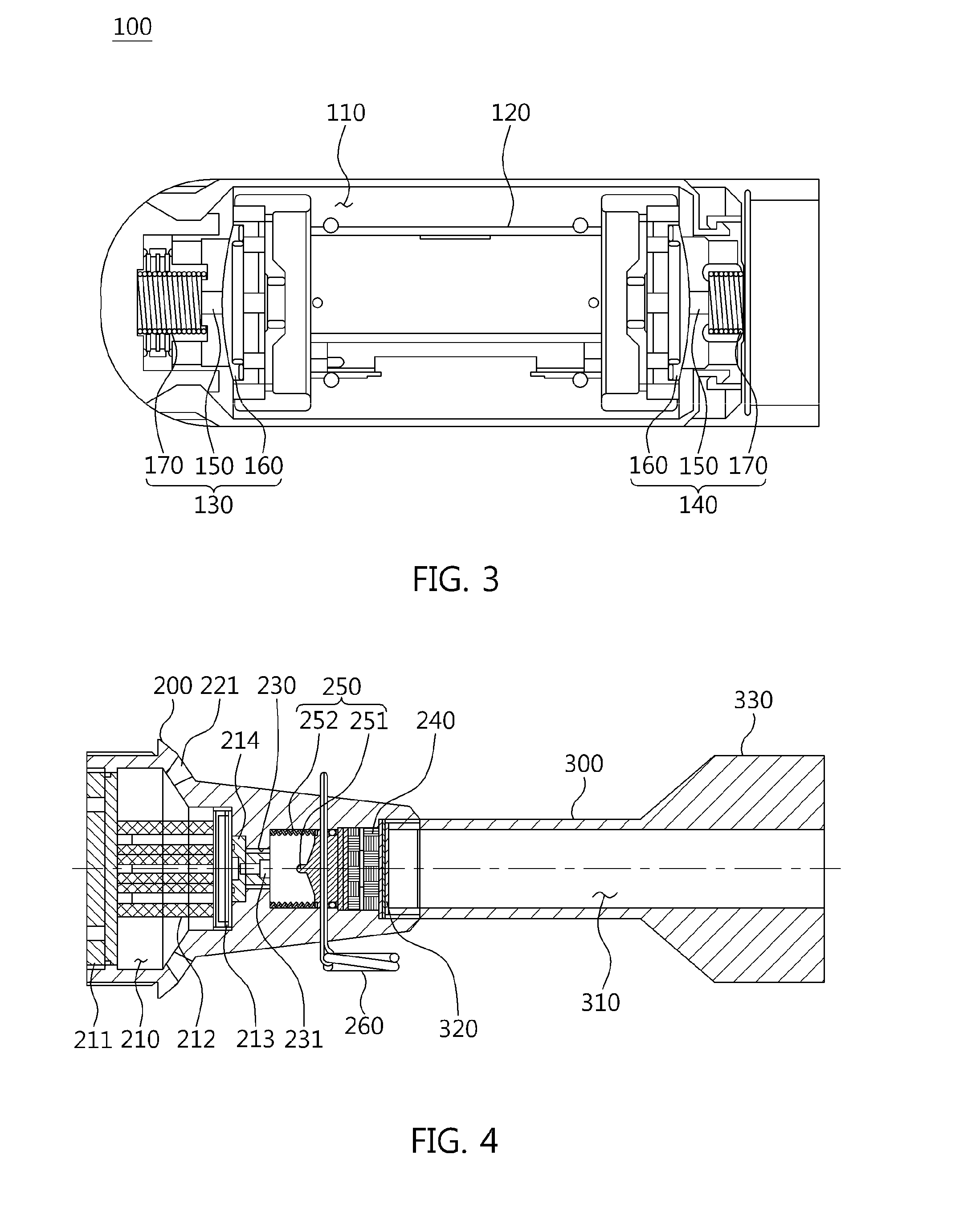
[0059]FIG. 1 is a diagram schematically illustrating a rifle grenade using a bullet trap according to the present invention, and FIG. 2 is a diagram schematically illustrating a cross section of the rifle grenade using the bullet trap according to the present invention.

[0060]According to the present invention, a long-range rifle grenade which uses a trap of a bullet B and has a warhead mounted with a robot 400 includes a propellent assemb...


PUM


Abstract

Disclosed is a rifle grenade using a bullet trap. A propellent assembly is formed with a first housing configured to house a trapping unit that traps a bullet shot from a gun to travel from rear to front and absorbs kinetic energy of the bullet, and a second housing configured to house a propelling unit that is disposed in front of the first housing, and is activated by the kinetic energy of the bullet which is absorbed into the trapping unit to provide a propelling force in a trajectory direction of the rifle grenade.

Description

CROSS REFERENCE TO RELATED APPLICATION(S)[0001]This application claims the benefit of Korean Patent Application No. 10-2013-0100489, filed on Aug. 23, 2013, which is hereby incorporated by reference in its entirety into this application.BACKGROUND OF THE INVENTION[0002]1. Technical Field[0003]The present invention relates generally to a rifle grenade using a bullet trap and, more particularly, to a rifle grenade using a bullet trap, which is loaded on a gun such as a rifle, allows a robot mounted in a protective shell to be discharged toward a target by kinetic energy of a fired bullet, and generates a propelling force from the kinetic energy of the bullet so as to be able to be aimed and fired at a more distant target.[0004]2. Description of the Related Art[0005]A rifle grenade is loaded on a muzzle of a rifle that is an individual weapon for the purpose of causing casualties or destroying major facilities when small units fight in combat at a short range, and is directly or indire...

Claims


Application Information

Patent Timeline
Patent Type & Authority Applications(United States)
IPC IPC(8): F42B30/06F42B10/06
CPCF42B10/06F42B30/06F41H7/005F42B12/58F42B12/625
Inventor RHEE, JOON SEONGPARK, MIN SUPARK, SOON SUKSHIN, JUN GOO
Owner HANWHA AEROSPACE CO LTD
Learn More