

Substrate storage container
- Summary
- Abstract
- Description
- Claims
- Application Information
AI Technical Summary
Benefits of technology
Problems solved by technology
Method used
Image

Examples
first embodiment
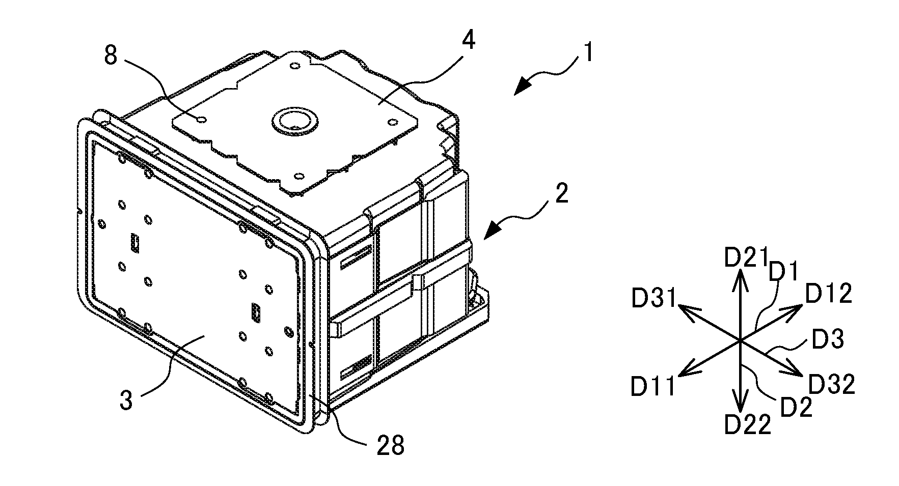
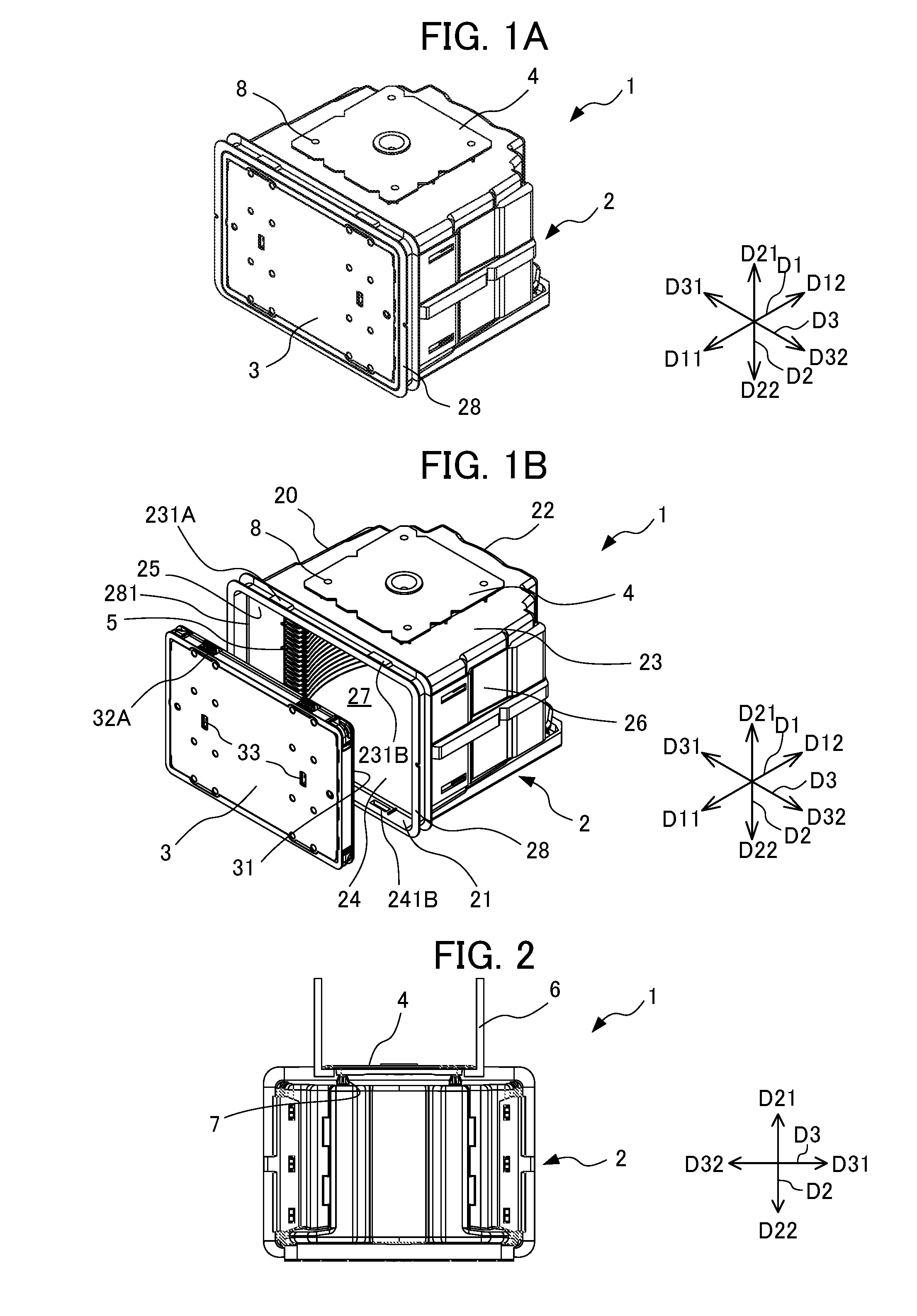
[0041]As illustrated in FIGS. 1A and 1B, the wall portion 20 of the container main body 2 includes a back wall 22, an upper wall 23, a lower wall 24, a first side wall 25, and a second side wall 26. The back wall 22, the upper wall 23, the lower wall 24, the first side wall 25, and the second side wall 26 are made of a plastic material, etc., and are configured so as to be integrally molded with polycarbonate in the
[0042]The first side wall 25 faces the second side wall 26 and the upper wall 23 faces the lower wall 24. A rear end of the upper wall 23, a rear end of the lower wall 24, a rear end of the first side wall 25, and a rear end of the second side wall 26 are all connected to the back wall 22. A front end of the upper wall 23, a front end of the lower wall 24, a front end of the first side wall 25, and a front end of the second side wall 26 have a positional relationship opposite the back wall 22, and configure an opening rim portion 28 which forms the container main body ope...
embodiment 1
[0057]In accordance with the substrate storing container 1 according to the present embodiment 1 with the abovementioned configuration, the following effect can be obtained.
[0058]A substrate storing container 1 that stores substrates composed of semiconductor wafers includes: a container main body 2 including a tubular wall portion 20 having a container main body opening portion 21 formed at one end and the other end being closed, the wall portion 20 including a back wall 22, an upper wall 23, a lower wall 24, and the first side wall 25 and the second side wall 26 as a pair of side walls, at which the container main body opening portion 21 is formed by one end of the upper wall 23, one end of the lower wall 24, and one end of the first side wall 25 and one end of the second side wall 26 as a pair of the side walls, in which an inner face of the upper wall 23, an inner face of the lower wall 24, inner faces of the first side wall 25 and the second side wall 26 as the side walls, and ...
second embodiment
[0064]As illustrated in FIGS. 4A and 4B, in the second embodiment, the lower face of the elastic member 42A has a plurality of convex portions 423A in a linear shape which are formed radially from the center of the lower face of the elastic member 42A, and the arm 6 of the wafer transport apparatus serving as a lifting member can abut the convex portions 423A.
[0065]When transporting the substrate storing container 1, the arm 6 of the wafer transport apparatus abuts a plurality of convex portions 423A in a linear shape provided at the lower face of the elastic member 42A of the top flange 4. The plurality of convex portions 423A which abuts the arm 6 has an effect of preventing slipping relative to the arm 6 of the wafer transport apparatus. With such a configuration, when transporting the substrate storing container 1, the arm 6 of the wafer transport apparatus can sandwich the substrate storing container 1 in a state that does not easily slip in the forward / backward direction D1 an...
PUM
 Abstract
Description
Claims
Application Information