Group-III nitride substrate containing carbon at a surface region thereof

a nitride substrate and surface region technology, applied in the direction of polycrystalline material growth, crystal growth process, chemically reactive gas, etc., can solve the problems of dislocation defect propagation and cracking in the device layer, and achieve the effect of controlled lattice constant and low resistan

Active Publication Date: 2022-07-26
PANASONIC HLDG CORP +1
View PDF8 Cites 0 Cited by
  • Summary
  • Abstract
  • Description
  • Claims
  • Application Information

AI Technical Summary

Benefits of technology

[0007]An object of the present disclosure is to provide a group-III nitride substrate having a low resistance and a controlled lattice constant.
[0017]The group-III nitride substrate and the method of manufacturing the same according to the present invention can achieve both the resistance reduction and the lattice constant control of the group-III nitride substrate and can suppress propagation of dislocation defects and occurrence of cracking at the time of a subsequent step, i.e., device layer formation.

Problems solved by technology

However, a current substrate manufacturing method comprising mixing of impurities such as oxygen and silicon as a donor for lowering the resistance has a problem that simply mixing the impurities changes the lattice constant of the group-III nitride crystal and causes propagation of dislocation defects and cracking in a device layer at the time of a subsequent step, i.e., device layer formation, using a metal organic chemical vapor deposition (MOCVD) method etc.

Method used


Image

  • Group-III nitride substrate containing carbon at a surface region thereof
  • Group-III nitride substrate containing carbon at a surface region thereof
  • Group-III nitride substrate containing carbon at a surface region thereof

Examples


first embodiment

Overview of Group-III Nitride Substrate with Specified Surface Carbon Concentration and Oxygen Concentration

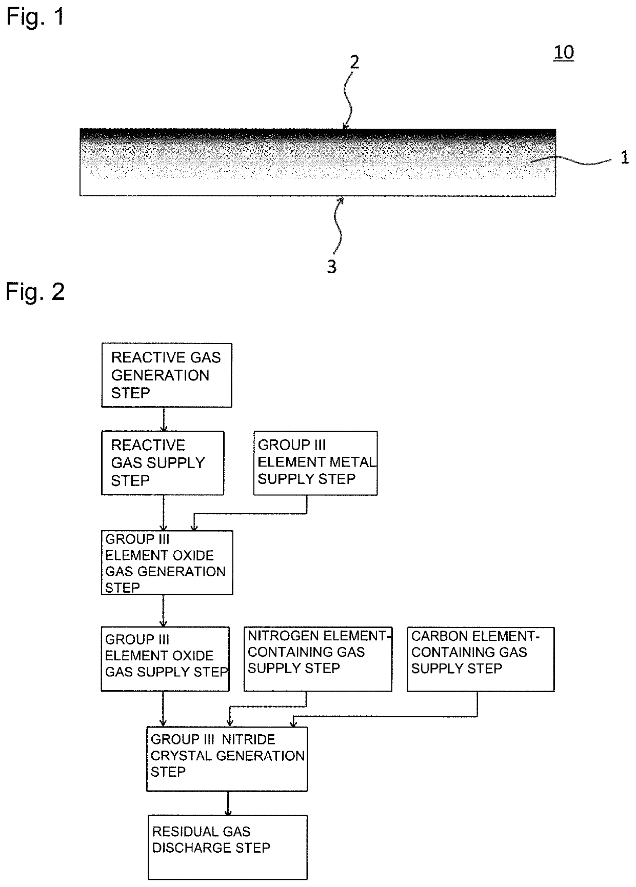
[0048]FIG. 1 is a schematic cross-sectional view of an example of a group-III nitride substrate according to a first embodiment. This group-III nitride substrate will be described with reference to the schematic cross-sectional view of FIG. 1. As shown in FIG. 1, a group-III nitride substrate 10 has a base material part 1 made of a group-III nitride having a front surface 2 and a back surface 3 and is characterized in that the front surface 2 has a carbon concentration controlled to a higher concentration as compared to an inner layer of the base material part 1. It is noted that the base material part 1 may correspond to a part of the group-III nitride substrate, or the base material part 1 may correspond to the whole of the group-III nitride substrate.

[0049]Controlling the carbon concentration of the front surface 2 in this way makes a reduction in resistance and control of ...

example 1

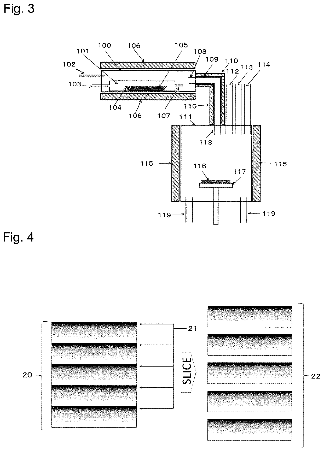
[0084]A group-III nitride crystal was grown by using the growth furnace shown in FIG. 3. GaN was grown as the group-III nitride crystal. Ga2O3 powder was used as a starting Ga source, Ga2O3 was reacted with the H2 gas that is a reactive gas, and the Ga2O gas was used as a Ga source gas. The NH3 gas was used as an N source. The H2 gas and the N2 gas were used as carrier gases. The CH4 gas was used as a carbon element-containing gas. Main crystal growth conditions are as follows. A partial pressure of each gas in this case is a partial pressure of each gas at the time of supply into a chamber. The growth was entirely conducted in the atmosphere under the atmospheric pressure.

Growth Conditions of Base Material Part

[0085]Growth temperature: 1200° C., Raw material temperature: 1100° C., NH3 partial pressure: 0.04 atm, H2 partial pressure: 0.89 atm, CH4 partial pressure: 0.01 atm

Growth Conditions of Front Surface of Base Material Part

[0086]Growth temperature: 1200° C., Raw material temper...


PUM

PropertyMeasurementUnit
temperatureaaaaaaaaaa
boiling pointaaaaaaaaaa
temperatureaaaaaaaaaa

Abstract

A group-III nitride substrate includes: a base material part of a group-III nitride including a front surface, a back surface, and an inner layer between the front surface and the back surface, wherein the carbon concentration of the front surface of the base material part is higher than the carbon concentration of the inner layer.

Description

CROSS-REFERENCE TO RELATED APPLICATIONS[0001]This application claims priority of Japanese Patent Application No. 2018-131691 filed on Jul. 11, 2018, the contents of which is incorporated herein by reference.BACKGROUND OF THE INVENTION1. Field of the Invention[0002]The present disclosure relates to a group-III nitride substrate and a method of manufacturing the same.2. Description of the Related Art[0003]Group-III nitride crystals of GaN etc. are expected to be applied to next-generation optical devices such as high-output LEDs (light emitting diodes) and LDs (laser diodes), and next-generation electronic devices such as high-output power transistors mounted on EVs (electric vehicles) and PHVs (plug-in hybrid vehicles).[0004]To improve performance of optical / electronic devices using group-III nitride crystals, a substrate serving as a base material is desirably made up of a high-quality group-III nitride single crystal substrate of GaN etc. To achieve higher quality of the substrate,...

Claims


Application Information

Patent Timeline
Patent Type & Authority Patents(United States)
IPC IPC(8): C30B29/40C30B25/14C30B25/10C30B25/08
CPCC30B29/406C30B25/08C30B25/10C30B25/14C23C16/303C23C16/455C30B25/165C30B25/02
Inventor MORI, YUSUKEYOSHIMURA, MASASHIIMANISHI, MASAYUKIKITAMOTO, AKIRATAKINO, JUNICHISUMI, TOMOAKIOKAYAMA, YOSHIO
Owner PANASONIC HLDG CORP
Why Eureka
Try Eureka