Audio signal amplification device, power supply device, and power supply control method

Active Publication Date: 2017-09-28
PANASONIC INTELLECTUAL PROPERTY MANAGEMENT CO LTD
View PDF5 Cites 0 Cited by
  • Summary
  • Abstract
  • Description
  • Claims
  • Application Information

AI Technical Summary

Benefits of technology

[0009]The audio signal amplification device, power supply device, and power supply control method of the present disclosure can suppress th

Problems solved by technology

Then, when the audio signal is amplified based on the clock generated by the clock generation circuit affected by the noise,

Method used


Image

  • Audio signal amplification device, power supply device, and power supply control method
  • Audio signal amplification device, power supply device, and power supply control method
  • Audio signal amplification device, power supply device, and power supply control method

Examples


Example

First Exemplary Embodiment

[0021]A description is made below of a first exemplary embodiment with reference to FIG. 1 to FIG. 5.

[0022][1-1. Configuration]

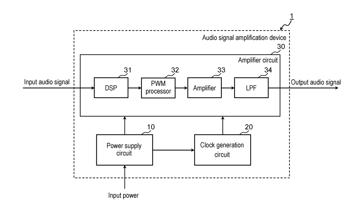
[0023]FIG. 1 is a block diagram schematically showing a configuration example of audio signal amplification device 1 in the first exemplary embodiment.

[0024]Audio signal amplification device 1 in this exemplary embodiment is an audio signal amplification device that amplifies an audio signal. Audio signal amplification device 1 includes power supply circuit 10, clock generation circuit 20, and amplifier circuit 30.

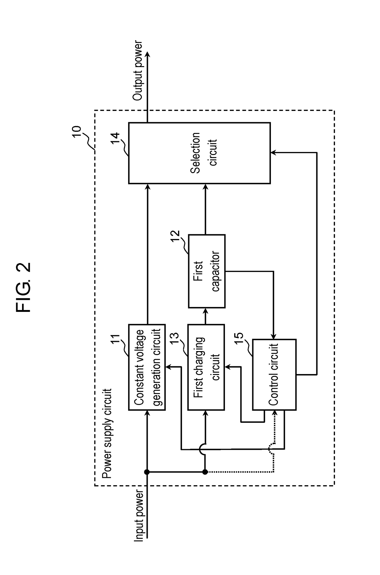
[0025]Power supply circuit 10 is a circuit that receives input power, which is supplied from a power supply (not shown) such as an alternating current power supply and a direct current power supply, and generates direct current power supplied to clock generation circuit 20 and amplifier circuit 30. Details of power supply circuit 10 will be described later.

[0026]Clock generation circuit 20 is a circuit that generates a clo...

Example

Second Exemplary Embodiment

[0148]A description is made below of a second exemplary embodiment with reference to FIG. 6 to FIG. 8.

[0149][2-1. Configuration]

[0150]A configuration and operations of audio signal amplification device 1a in the second exemplary embodiment are substantially same as those of audio signal amplification device 1 described in the first exemplary embodiment; however, audio signal amplification device 1a is different from audio signal amplification device 1 in that audio signal amplification device 1a includes power supply circuit 10a in place of power supply circuit 10. Hence, in the second exemplary embodiment, same reference numerals are assigned to substantially same constituent elements as the constituent elements described in the first exemplary embodiment, and a description of the constituent elements are omitted, and moreover, only reference numeral is assigned to audio signal amplification device 1a, and illustration regarding the configuration of audio...


PUM


Abstract

An audio signal amplification device includes: a clock generation circuit that generates a clock for use in amplifying an audio signal; and a power supply circuit that generates direct current power, which is supplied to the clock generation circuit, from input power. The power supply circuit includes: a constant voltage generation circuit that generates direct current power of a constant voltage from the input power; a first capacitor; a first charging circuit that charges the first capacitor by using the input power; and a selection circuit. The selection circuit selects one direct current power of the direct current power generated in the constant voltage generation circuit and of direct current power charged to the first capacitor, and supplies the selected direct current power to the clock generation circuit.

Description

TECHNICAL FIELD[0001]The present disclosure relates to an audio signal amplification device, a power supply device, and a power supply control method.BACKGROUND ART[0002]Patent Literature 1 discloses an audio signal amplification device that amplifies an audio signal and the like.[0003]As the audio signal amplification device, there is known a D-class amplifier with a little loss, which is capable of reducing power consumption. Moreover, there is known an audio signal amplification device including a clock generation circuit that generates a clock for use in amplifying the audio signal. In such an audio signal amplification device as described above, noise generated in a power supply circuit that supplies electric power to the clock generation circuit sometimes propagates to the clock generation circuit. Then, when the audio signal is amplified based on the clock generated by the clock generation circuit affected by the noise, distortion of an output signal is increased, causing a d...

Claims


Application Information

Patent Timeline
IPC IPC(8): H03F3/217H04R3/04G10K11/00H03F1/26
CPCH03F3/217G10K11/002H04R3/04H03F1/26H03F1/30H03F3/181H03F2200/03H03F2200/321H03F2200/351H03F2200/511H03L1/00H04R3/00
Inventor OKUDA, TADAYOSHI
Owner PANASONIC INTELLECTUAL PROPERTY MANAGEMENT CO LTD
Why Eureka
Try Eureka