Eureka AIR delivers breakthrough ideas for toughest innovation challenges, trusted by R&D personnel around the world.

Pivotal assembly for hand tool

Inactive Publication Date: 2016-08-11
LEE CHIH MING
View PDF0 Cites 2 Cited by
  • Summary
  • Abstract
  • Description
  • Claims
  • Application Information

AI Technical Summary

Benefits of technology

The present invention is a hand tool that has a pivotal portion with a U-shaped recess. The tool has multiple engaging teeth and a pawl with two recesses. The pawl has curved faces that engage with the engaging teeth. The tool also has a controller with grooves and stop faces that determine its position. The technical effect of this invention is to provide a hand tool that can securely engage and disengage with the engagement teeth for efficient use in various applications.

Problems solved by technology

However, when the ratchet head is pivoted relative to the handle at an angle, the block and the shaft contacts each other at only one contact face, so that the ratchet head is not stable at the angled position.

Method used


Image

  • Pivotal assembly for hand tool
  • Pivotal assembly for hand tool
  • Pivotal assembly for hand tool

Examples


Embodiment Construction

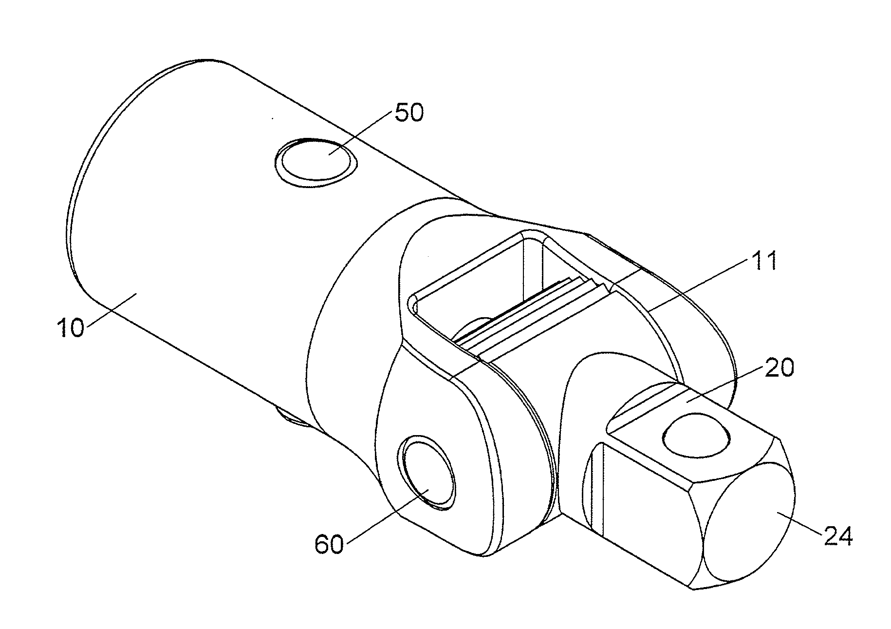
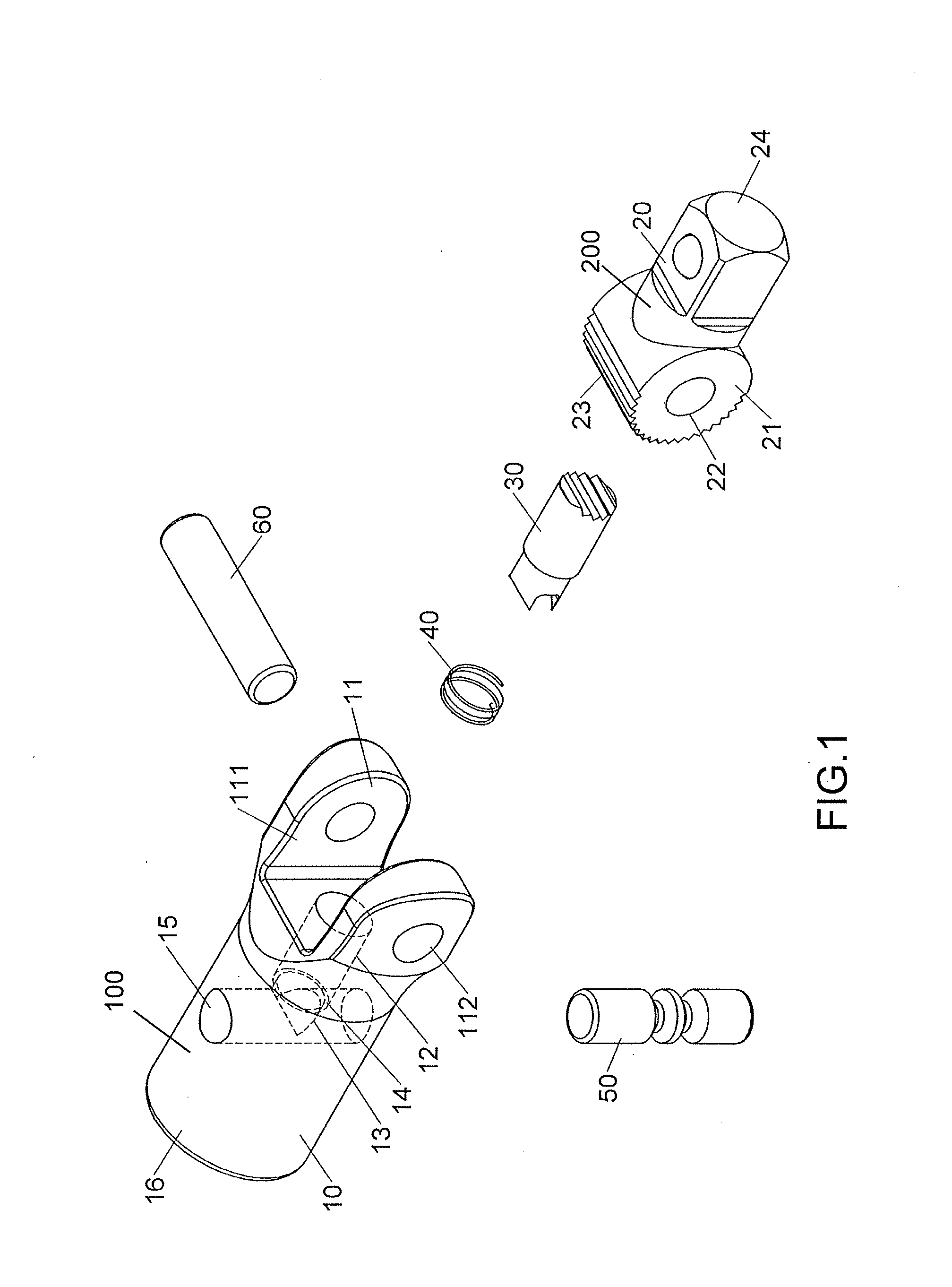
[0024]Referring to FIGS. 1 to 8, the hand tool of the present invention comprises a body 10 having a pivotal portion 11 on one end thereof, wherein the pivotal portion 11 has a U-shaped recess 111 between two extensions. A hole 112 is defined through each of the two extensions of the pivotal portion 11. A first recess 12 extends axially from the inner end of the U-shaped recess 111 along the body 10, and communicates with the U-shaped recess. A third recess 15 is radially defined through the body 10 and communicates with the first recess 12. A second recess 13 communicates between the first and third recesses 12, 15. The radius of the second recess 13 is smaller than the radius of the first recess 12 so that a first contact face 14 is formed at the conjunction portion between the first and second recesses 12, 13. The second recess 13 communicates with a middle portion of the third recess 15 and one end of the first recess 12. The two ends of the third recess 15 open through the oute...


PUM


Abstract

A hand tool includes a body and a ratchet head which is pivotably connected to the body. A pawl and a controller are connected to the body. The ratchet head is engaged with the pawl by first and second engaging teeth. The controller has a recess which has two curved faces. The controller has two grooves and each groove has a first stop face and a second stop face. The first and second stop faces contact the two curved faces. The pawl is not moveable, and the first engaging teeth are engaged with the second engaging teeth so as to fix the ratchet head relative to the body at an angle. When the two curved faces are moved to face the two grooves, the controller is moved, and the ratchet head is pivotable relative to the body.

Description

BACKGROUND OF THE INVENTION[0001]1. Fields of the invention[0002]The present invention relates to a hand tool, and more particularly, to a pivotal assembly for controlling the angle of the ratchet head relative to the handle.[0003]2. Descriptions of Related Art[0004]The conventional ratchet wrench such as disclosed in U.S. Pat. No. 6,131,490 comprises a ratchet head having a neck portion and a ratchet portion, a handle having an end recess receiving the neck portion, and a sleeve receiving a portion of the handle. A pivot pin fastens the ratchet head and the handle together. A first retainer ring surrounds a first end of the sleeve. The first retainer ring has an eccentric hole. An end plug plugs a second end of the sleeve. The handle has a first blind hole receiving a first spring and a first positioning ball, a second blind hole receiving a second spring and a first positioning pin, a recess hole receiving a second positioning ball, a first groove receiving a compression spring, a...

Claims


Application Information

Patent Timeline
IPC IPC(8): B25B23/00B25G1/06B25B13/46
CPCB25B13/461B25G1/063B25B13/463B25B23/0028
Inventor LEE, CHIH-MING
Owner LEE CHIH MING
Why Eureka
Eureka Blog
Learn More