

Deployable decelerator
a technology of decelerator and deceleration device, which is applied in the direction of braking system, locomotive, way, etc., to achieve the effect of stable manner
- Summary
- Abstract
- Description
- Claims
- Application Information
AI Technical Summary
Benefits of technology
Problems solved by technology
Method used
Image

Examples
Embodiment Construction
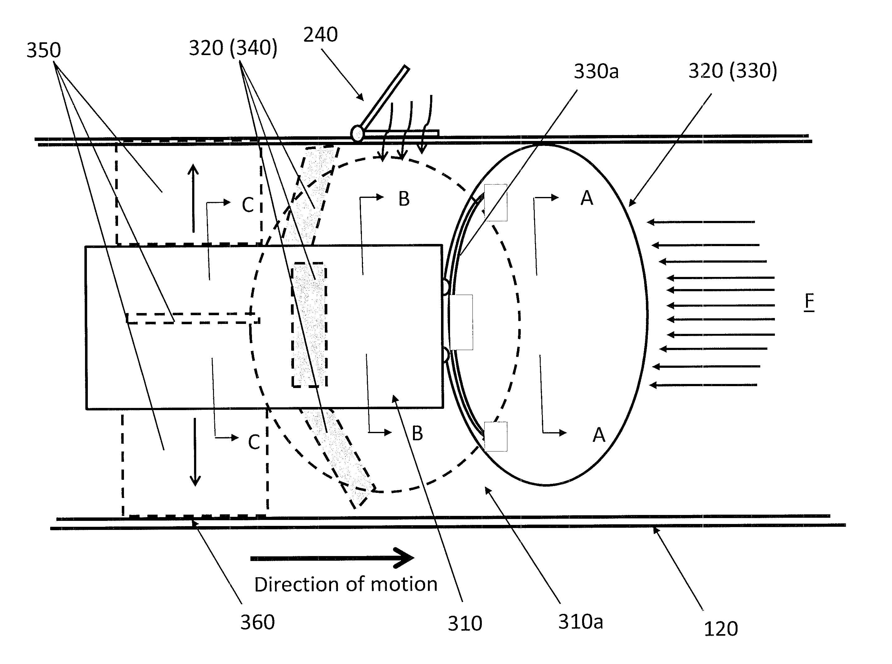
[0004]Because of these high speeds, conventional braking systems and methods are impractical. Current practices do not envision a transport vehicle, method or system that create a sustainable frictional braking system designed to handle the immense forces that would be produced by attempting to decelerate the vehicle to a slower speed or a complete stop because current transportation vehicles and systems do not operate at the speed that a partially-evacuated, low-pressure environment allows. Thus, there is a need to design a transport vehicle, a deceleration method and a deceleration system that allow transport vehicles operating at elevated speeds within a low-pressure environment structure (e.g., a transport tube) to decelerate safely and in a stable manner.
[0005]According to non-limiting embodiments of the present application, a transport vehicle for traveling in a low-pressure environment structure is provided. The transport vehicle may include a deployable decelerator provided ...
PUM
 Abstract
Description
Claims
Application Information