Method of manufacturing optical fiber, optical fiber manufacturing apparatus, and control apparatus therefor

Active Publication Date: 2016-08-11
THE FUJIKURA CABLE WORKS LTD
View PDF3 Cites 6 Cited by
  • Summary
  • Abstract
  • Description
  • Claims
  • Application Information

AI Technical Summary

Benefits of technology

[0031]According to the aspects of the invention, since the path length of the bare optical fiber is adjusted by controlling the position of the direction changer based on a measurement value of an outer diameter of the coated layer an optical fiber production intermediate, the temperature of the bare optical fiber which is introduced into the coating unit is adjusted with a high level of accuracy, and it is possible to maintain the outer diameter of

Problems solved by technology

The overall height of the system thereof is limited and becomes a factor that affects the productivity of the manufacturing method.
Because the height of the system becomes a main factor that limits the productivity, it is necessary to ensure the distance of a bare optical fiber in the system which is required to sufficiently cool the bare optical fiber obtained by drawing it from an optical fiber preform.
The above-described limitation can be eased by construction of new facilities such as new buildings; however, a huge cost is necessary in order to ease the limitation, if improvement in productivity is required in the future, it will be necessary

Method used


Image

  • Method of manufacturing optical fiber, optical fiber manufacturing apparatus, and control apparatus therefor
  • Method of manufacturing optical fiber, optical fiber manufacturing apparatus, and control apparatus therefor
  • Method of manufacturing optical fiber, optical fiber manufacturing apparatus, and control apparatus therefor

Examples


example 1

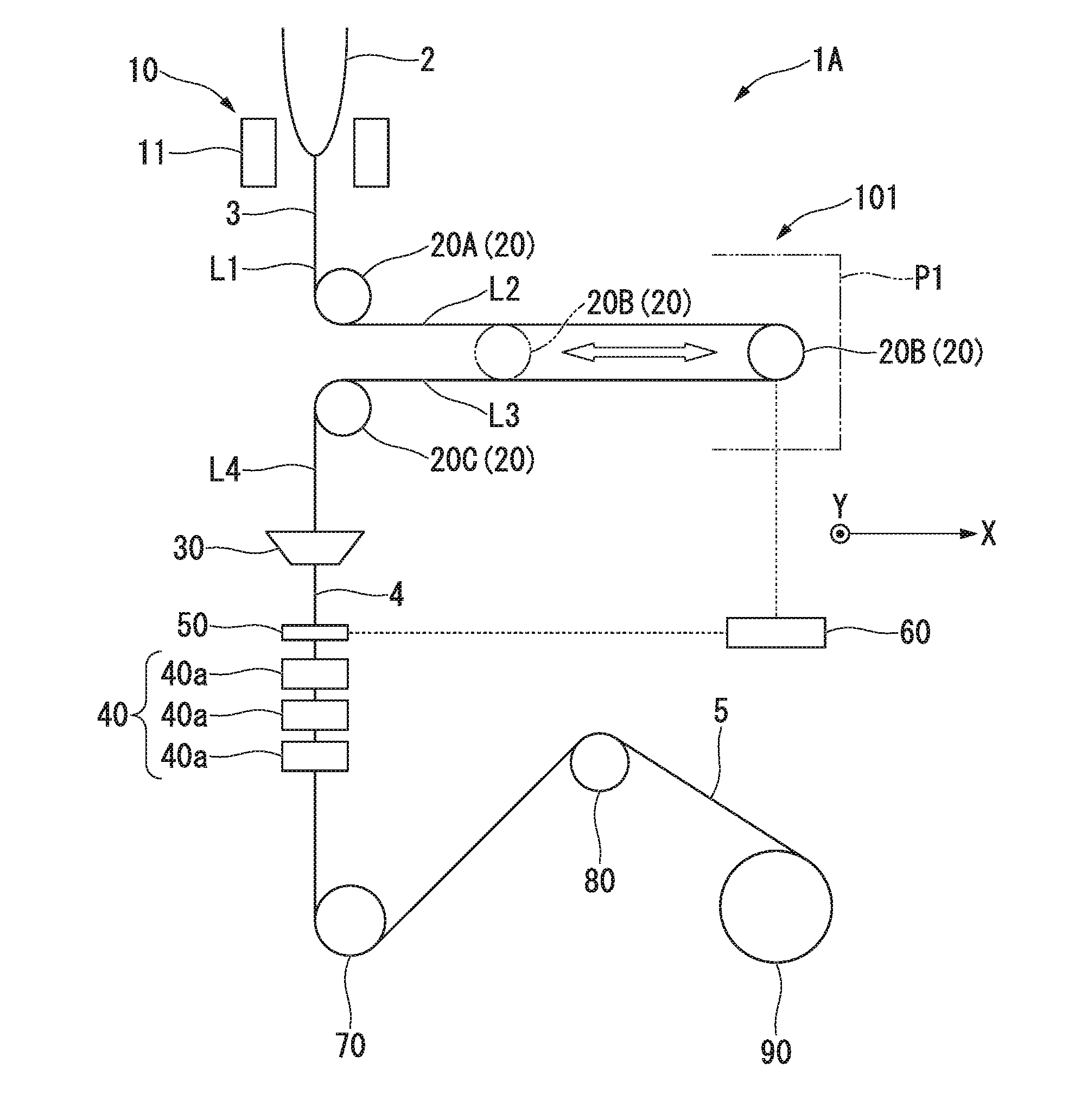
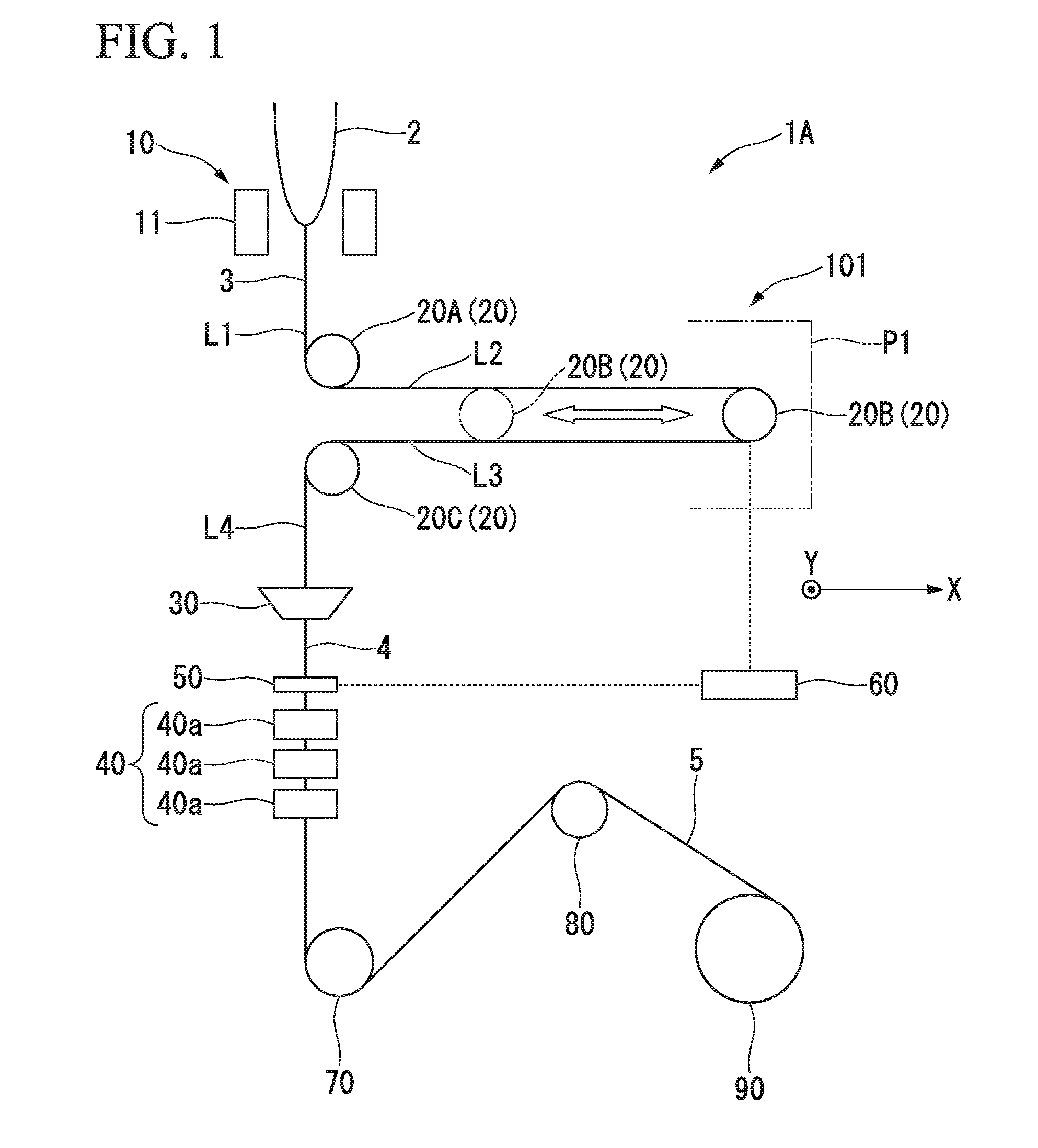
[0233]The manufacturing apparatus 1A shown in FIG. 1 was prepared.

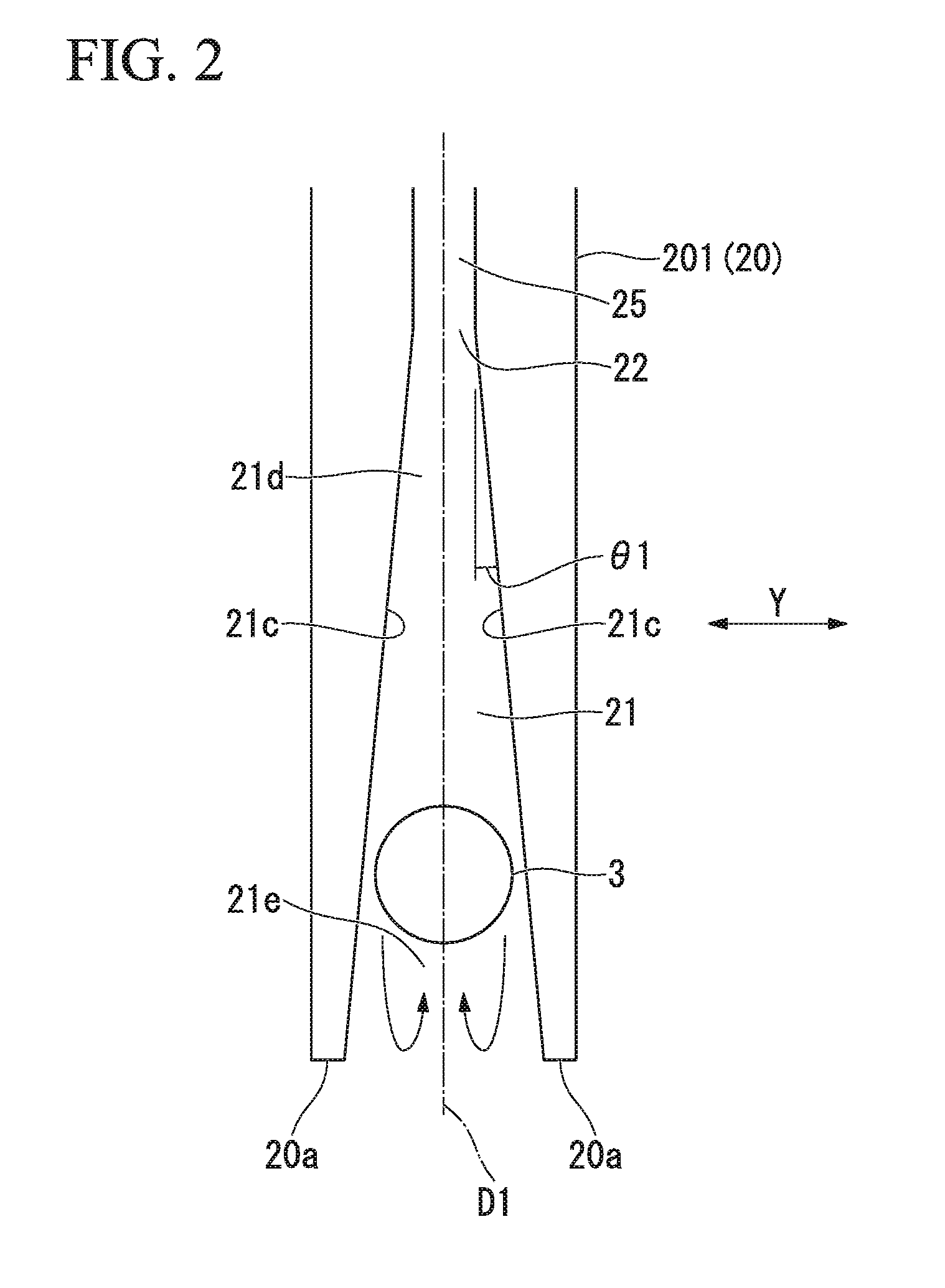
[0234]As the first direction changer 20A and the third direction changer 20C, the direction changer 201 shown in FIG. 3 was used.

[0235]As the second direction changer 20B, the direction changer 203 shown in FIG. 5 was used.

[0236]A width of the guide groove 21 was 145 μm.

[0237]A flotation turning radius of the bare optical fiber 3 was approximately 62.5 mm.

[0238]Fluid which is to be introduced into the direction changers 20A and 2013 is air, and the temperature thereof was at a room temperature (approximately 24° C.).

[0239]The introduction flow rate of air into each of the first direction changer 20A and the third direction changer 20C was 100 liters per minute. An introduction flow rate of air into the second direction changer 20B was 200 liters per minute.

[0240]The first direction changer 20A was provided at the position at which the temperature of the bare optical fiber 3 becomes approximately 1000° C.

[0241]The bare...

example 2

[0252]The manufacturing apparatus 1B shown in FIG. 7 was prepared.

[0253]The pick-up unit 70 measured a drawing velocity of the optical fiber 5 and carried out control such that: in the case where the drawing velocity of the optical fiber 5 decreases, the second direction changer 20B comes close to the first direction changer 20A and the third direction changer 20C; in the case where a drawing velocity of the optical fiber 5 increases, the second direction changer 20B moves separately from the first direction changer 20A and the third direction changer 20C.

[0254]In this Example, the optical fiber 5 was manufactured under the control condition described above, and the condition other than the above-described condition was the same as that of Example 1.

[0255]In the manufacturing method, flotation of the bare optical fiber 3 was stabilized in the direction changers 20A to 20C.

[0256]In the manufacture of the optical fiber, a drawing velocity of the optical fiber 5 varied at ±1 m / second; ...

example 3

[0258]The manufacturing apparatus ID shown in FIG. 9 was prepared.

[0259]The direction changer 201 shown in FIG. 3 was used as the direction changers 20A and 20F.

[0260]The direction changer 203 shown in FIG. 5 was used as the direction changers 20B, 20D, and 20E.

[0261]The first direction changer 20A was provided at the position at which the temperature of the bare optical fiber 3 becomes approximately 800° C.

[0262]The bare optical fiber 3 (outer diameter of 125 μm) was obtained by drawing the optical fiber from the optical fiber preform 2 in the drawing unit 10.

[0263]As a drawing speed and a drawing tension, a common condition (drawing speed of 40 m / second and a drawing tension of approximately 150 gf) was adopted.

[0264]The direction of the bare optical fiber 3 that is drawn from the optical fiber preform 2 in the downward vertical direction (first pathway L1) is changed by 90 degrees by the first direction changer 20A to be in the horizontal direction (second pathway L2). Subsequent...


PUM


Abstract

A method of manufacturing an optical fiber of the invention includes: preparing a direction changer; drawing the bare optical fiber from an optical fiber preform; providing a coated layer on a periphery of the bare optical fiber; obtaining an optical fiber by curing the coated layer; changing a direction of the bare optical fiber at a position between a bare-optical-fiber formation position and a coated-layer provision position; and measuring the outer diameter of the coated layer; and adjusting the length of the bare optical fiber from a drawing unit to a coating unit by controlling a position of the direction changer based on a measurement value of the outer diameter, the drawing unit forming the bare optical fiber, the coating unit providing the coated layer on the periphery of the bare optical fiber.

Description

CROSS REFERENCE TO RELATED APPLICATIONS[0001]This application claims priority from Japanese Patent Application No. 2015-024648 filed on Feb. 10, 2015, the contents of which are incorporated herein by reference.BACKGROUND OF THE INVENTION[0002]1. Field of the Invention[0003]The present invention relates to a method of manufacturing an optical fiber, an optical fiber manufacturing apparatus, and a control apparatus that controls the manufacturing apparatus.[0004]2. Description of the Related Art[0005]Generally, in manufacture of an optical fiber, a method is employed which vertically and downwardly draws an optical fiber from an optical fiber preform along a linear pathway.[0006]The overall height of the system thereof is limited and becomes a factor that affects the productivity of the manufacturing method.[0007]Because the height of the system becomes a main factor that limits the productivity, it is necessary to ensure the distance of a bare optical fiber in the system which is req...

Claims


Application Information

Patent Timeline
IPC IPC(8): C03B37/025C03B37/03C03C25/10G02B6/02
CPCC03B37/0253G02B6/02395Y02P40/57C03C25/106C03C2218/32C03B37/03C03B37/025C03C25/12C03C25/6226C03B37/02718C03B37/032G02B6/00
Inventor OKADA, KENJI
Owner THE FUJIKURA CABLE WORKS LTD
Why Eureka
Try Eureka