
Impeller suspension mechanism for heart pump

Active Publication Date: 2016-08-18
TC1 LLC
View PDF1 Cites 17 Cited by
  • Summary
  • Abstract
  • Description
  • Claims
  • Application Information

AI Technical Summary

Benefits of technology

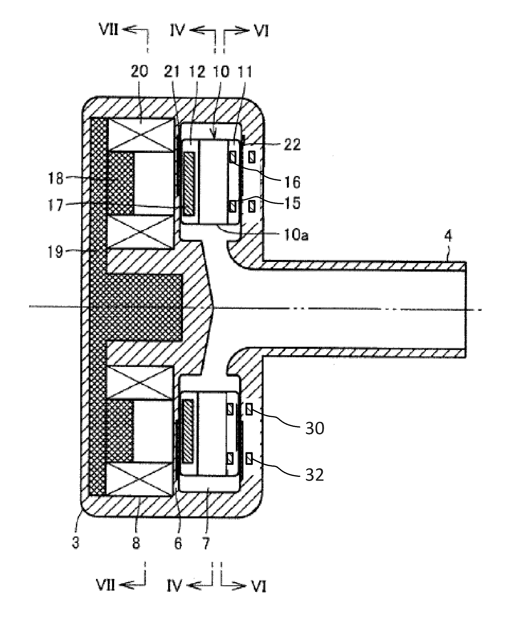
The patent text describes a centrifugal blood pump with an impeller and magnets that rotate together within a housing to transfer blood from inlet to outlet. The pump includes a motor to control the impeller movement, which results in the creation of a net magnetic force between the magnets and the inner and outer annular magnetic members in the housing. The force between the magnets and the annular magnetic members is greater in the inner portion of the impeller, and this force may be used to improve pump performance.

Problems solved by technology

However, in conventional pump designs, at high speeds the impeller tends to tilt, resulting in a decrease of a size of the gap near the outer edges of the impeller.

Method used


Image

  • Impeller suspension mechanism for heart pump
  • Impeller suspension mechanism for heart pump
  • Impeller suspension mechanism for heart pump

Examples


Embodiment Construction

[0021]The ensuing description provides exemplary embodiments only, and is not intended to limit the scope, applicability or configuration of the disclosure. Rather, the ensuing description of the exemplary embodiments will provide those skilled in the art with an enabling description for implementing one or more exemplary embodiments. It being understood that various changes may be made in the function and arrangement of elements without departing from the spirit and scope of the invention as set forth herein.

[0022]Specific details are given in the following description to provide a thorough understanding of the embodiments. However, it will be understood by one of ordinary skill in the art that the embodiments may be practiced without these specific details. For example, with regard to any specific embodiment discussed herein, any one or more details may or may not be present in all versions of that embodiment. Likewise, any detail from one embodiment may or may not be present in a...


PUM


Abstract

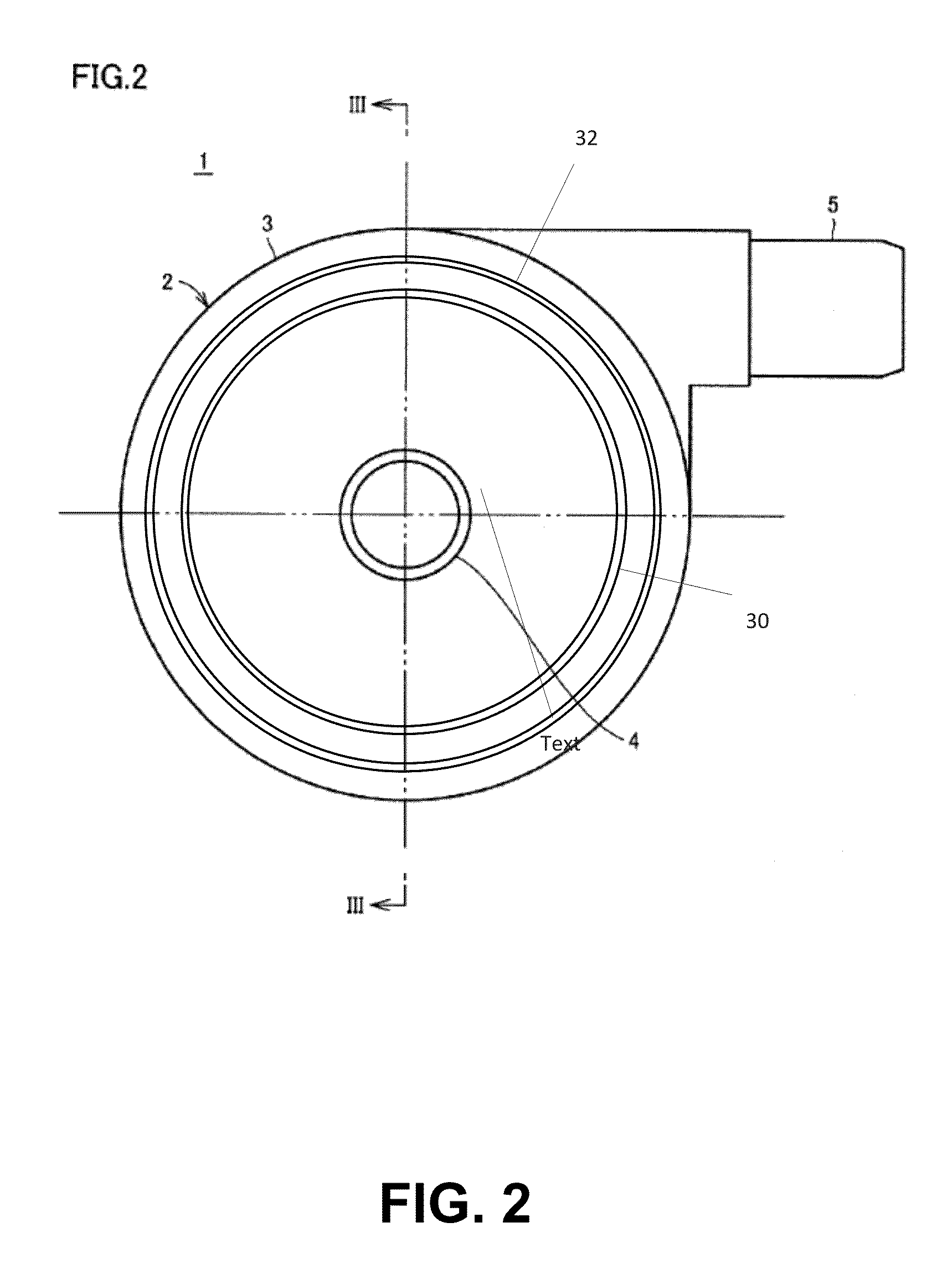
A centrifugal blood pump includes a housing that defines an inlet passage, a chamber, and an outlet passage. The pump includes an impeller rotatably positioned in the chamber to transfer blood from the inlet passage through the chamber and to the outlet passage and magnetic members embedded in the impeller such that the impeller and the magnetic members rotate together within the chamber. The pump includes a motor to control movement of the impeller in the chamber. The motor is adjacent the chamber and separated from the chamber by a partition member. The pump includes an inner annular magnetic member and an outer annular magnetic member embedded in a side of the housing opposite the partition member. A first net magnetic force between the inner annular magnetic member and the magnetic members exhibits greater attraction than a second net magnetic force between the outer annular member and the magnetic members.

Description

CROSS-REFERENCES TO RELATED APPLICATIONS[0001]This application claims priority to U.S. Provisional Application No. 62 / 115,741, filed Feb. 13, 2015 and entitled “IMPELLER SUSPENSION MECHANISM FOR HEART PUMP,” which is hereby incorporated by reference in its entirety.BACKGROUND OF THE INVENTION[0002]Conventional heart pumps utilize magnetic elements and / or hydrostatic bearings within a housing of the pump to compensate attractive forces produced by a stator motor to maintain an impeller of the pump in a desired position within a chamber of the pump. Such magnetic attractive forces from the magnetic elements provide negative stiffness. This negative stiffness increases as a distance between the magnetic elements within the housing and magnets on the impeller becomes shorter. Any tilt of the impeller will decrease a gap between the impeller and the wall of the chamber at an outer edge of the impeller. At low impeller speeds, hydrodynamic bearing forces are sufficient to maintain this ga...

Claims


Application Information

Patent Timeline
IPC IPC(8): A61M1/10F04D13/06F04D13/02F04D1/00A61M60/178A61M60/232A61M60/422A61M60/822A61M60/824
CPCA61M1/1036F04D1/00A61M1/1017F04D13/024F04D13/06F04D13/064F04D13/0666F04D29/047F04D29/048A61M60/824A61M60/422A61M60/148A61M60/232A61M60/178A61M60/822A61M60/419
Inventor YANAI, MASAMICHINANNA, JASON
Owner TC1 LLC
Learn More