Valve for a vacuum handling or vacuum clamping device, and vacuum handling means

a vacuum clamping device and vacuum handling technology, applied in the direction of valve arrangements, manipulators, gripping heads, etc., can solve the problems of pressure difference, pressure deficit in the control chamber with respect, compression of the control chamber, deformation of the dividing wall, etc., to prevent an undesired leakage and prevent thereby an undesired sensitivity to flow impacts

Active Publication Date: 2016-08-18
J SCHMALZ GMBH
View PDF6 Cites 0 Cited by
  • Summary
  • Abstract
  • Description
  • Claims
  • Application Information

AI Technical Summary

Benefits of technology

[0009]The invention addresses the object of preventing an undesired leakage between the vacuum supply side and the suction side when the suction side is unoccupied, and to pr

Problems solved by technology

As a result, when the suction side draws freely in an unoccupied state, the valve body is moved to the closed position due to a static pressure deficit with respect to the suction side that occurs in the control chamber.
If the suction side is unoccupied (drawing freely), then the comparatively large flow leads to a pressure difference via the fl

Method used


Image

  • Valve for a vacuum handling or vacuum clamping device, and vacuum handling means

Examples


Embodiment Construction

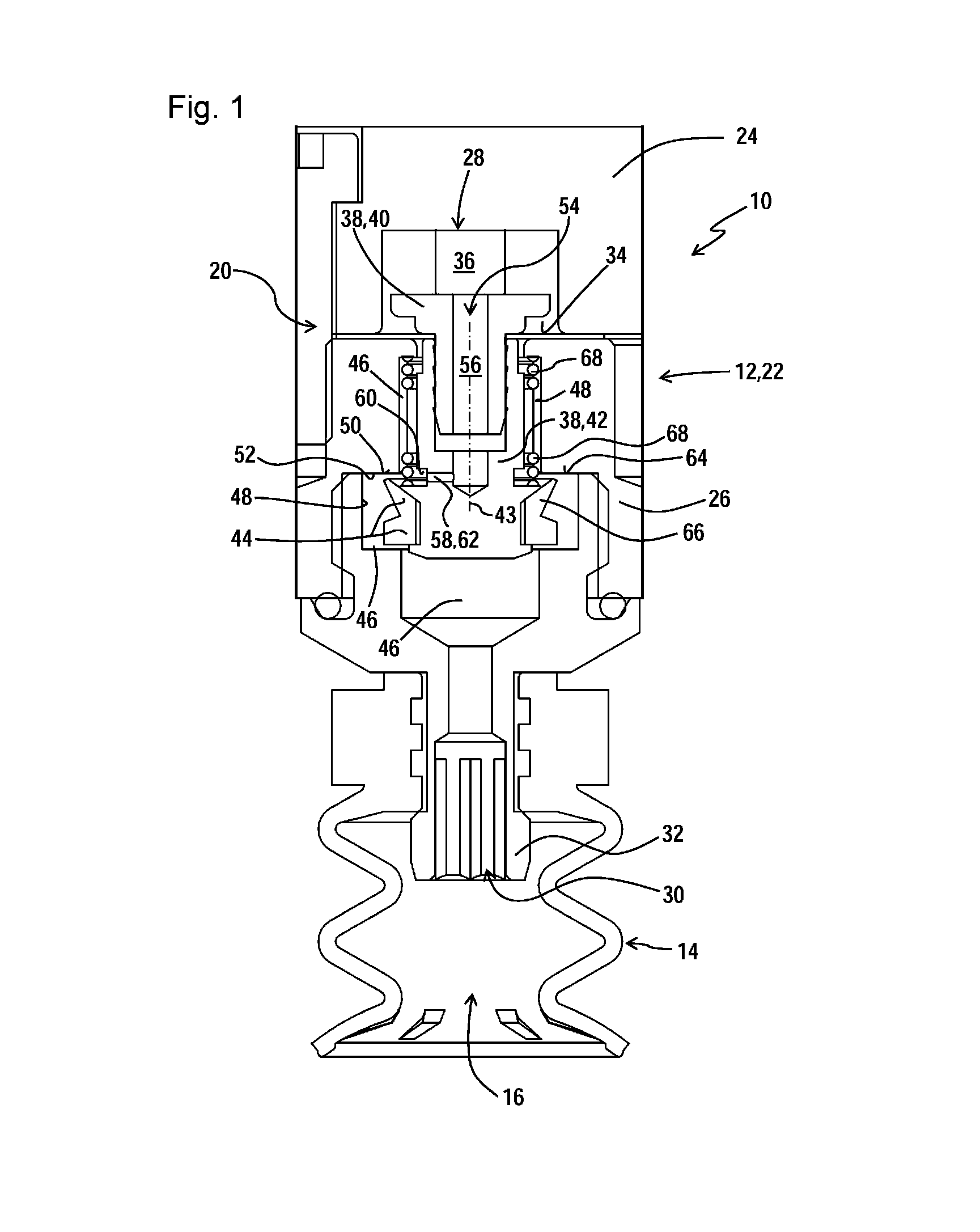
[0027]The suction gripper device 10 has a device housing 12, on which a suction body 14 is disposed such that it can be brought to bear on a workpiece that is to be gripped. As a matter of course, the suction gripper device 10 can also contain numerous suction bodies 14 disposed on the device housing 12.

[0028]The suction body 14 borders on a suction chamber 16 for suctioning a workpiece, which chamber is open in a suction direction. A valve 20 according to the invention, for controlling the vacuum supply of the suction chamber 16, is allocated to the suction body 14.

[0029]The valve 20 has a valve housing 22, which is formed in the depicted example by the part of the device housing 12 that can be recognized in FIG. 1. The valve housing 22 has a multi-part construction, having an upper part 24, and a lower part 26 connected thereto.

[0030]The upper part 24 of the valve housing 22 has a vacuum supply side 28, which communicates with a, not shown, vacuum supply device, such that the vacu...


PUM


Abstract

Valve with a valve housing which has a vacuum supply side and a suction side, with a flexible dividing wall which delimits a control space in the valve housing. A valve body which is arranged on the flexible dividing wall and can be moved between an open position and a closed position, wherein the valve body has a sealing portion which, in the closed position, bears against a sealing seat in order to seal the vacuum supply side with respect to the suction side. The volume of the control space is reduced with deformation of the flexible dividing wall and the valve body is moved from the open position into the closed position. The valve body has a suction side passage, and the sealing portion and the sealing seat are arranged in such a way that, in the closed position, the flow connection through the suction side passage is sealingly closed.

Description

CROSS-REFERENCE TO RELATED APPLICATIONS[0001]The present application is a National Stage of International Patent Application No. PCT / EP2014 / 069733, filed on Sep. 16, 2014, which claims priority to and all the benefits of German Patent Application No. 10 2013 222 378.1, filed on Nov. 4, 2013, both of which are hereby expressly incorporated herein by reference in their entirety.BACKGROUND OF THE INVENTION[0002]1. Field of the Invention[0003]The invention relates to a valve for vacuum handling devices or vacuum clamping devices. These are valves that close automatically when a suction point is unoccupied, and thus prevent an undesired leakage from the suction side to the vacuum supply side.[0004]2. Description of the Related Art[0005]Various solutions are known for preventing an undesired leakage when the suction point is unoccupied. By way of example, DE 34 29 444 A1 shows a flow control valve in which a valve body having a spherical design is disposed in a flow channel such that it c...

Claims


Application Information

Patent Timeline
IPC IPC(8): B25J15/06F16K1/12F16K51/02
CPCB25B11/005B65G47/91F16K51/02B25J15/0625F16K1/126B25B11/007
Inventor EISELE, THOMAS
Owner J SCHMALZ GMBH
Why Eureka
Try Eureka