
Active pen with tip pressure sensor

a technology of pressure sensor and active pen, which is applied in the direction of mechanical pattern conversion, graph reading, instruments, etc., can solve the problems of high detection error, knowledge of the pressure applied by the pen, and the quality of the position detection of the tip of the pen can only be detected with a high detection error

Inactive Publication Date: 2016-08-18
ADVANCED SILICON
View PDF8 Cites 8 Cited by
  • Summary
  • Abstract
  • Description
  • Claims
  • Application Information

AI Technical Summary

Benefits of technology

This patent text discusses leaf springs, which are easy to make and can be adapted to different needs. They create a smooth connection to the movable part, allowing for a wide range of force and sensitivity requirements. The use of a non-linear spring also allows for smaller force changes to cause larger tip displacement. Overall, this design provides greater flexibility and efficiency for a wide range of applications.

Problems solved by technology

Unfortunately, the quality of the position detection of touches reduces with the size of the touched surface.
Therefore, the quality of the position detection of a tip of a pen can only detected with a high detection error.
Another problem for a good detection of written interactions with touch devices is the knowledge of the pressure applied by the pen.
However, the state of the art solutions for pressure sensors have several drawbacks.
This increase the time for assembling the pen, complexity of the construction and robustness.
This increases the difficulty to detect the applied tip force with a high accuracy.
One problem is the normal use of spiral spring or other elastic elements which have a constant stiffness.
Since the displacement of the tip is only minimal, a realization can therefore either detect small forces with high accuracy, but not detect higher forces above a certain threshold anymore or detect a high range of forces up to high application forces with a low accuracy.
However, such a solution increases the complexity, size and robustness of the pressure sensor.
Spiral springs have further the problem that they are difficult to assemble and need much space.
Another problem regarding the detection accuracy is that the maximal displacement of the tip which is available for detecting the force applied is only small.
However, such a linear solution does not allow realizing a higher accuracy at small tip displacement.

Method used


Image

  • Active pen with tip pressure sensor
  • Active pen with tip pressure sensor
  • Active pen with tip pressure sensor

Examples


Embodiment Construction

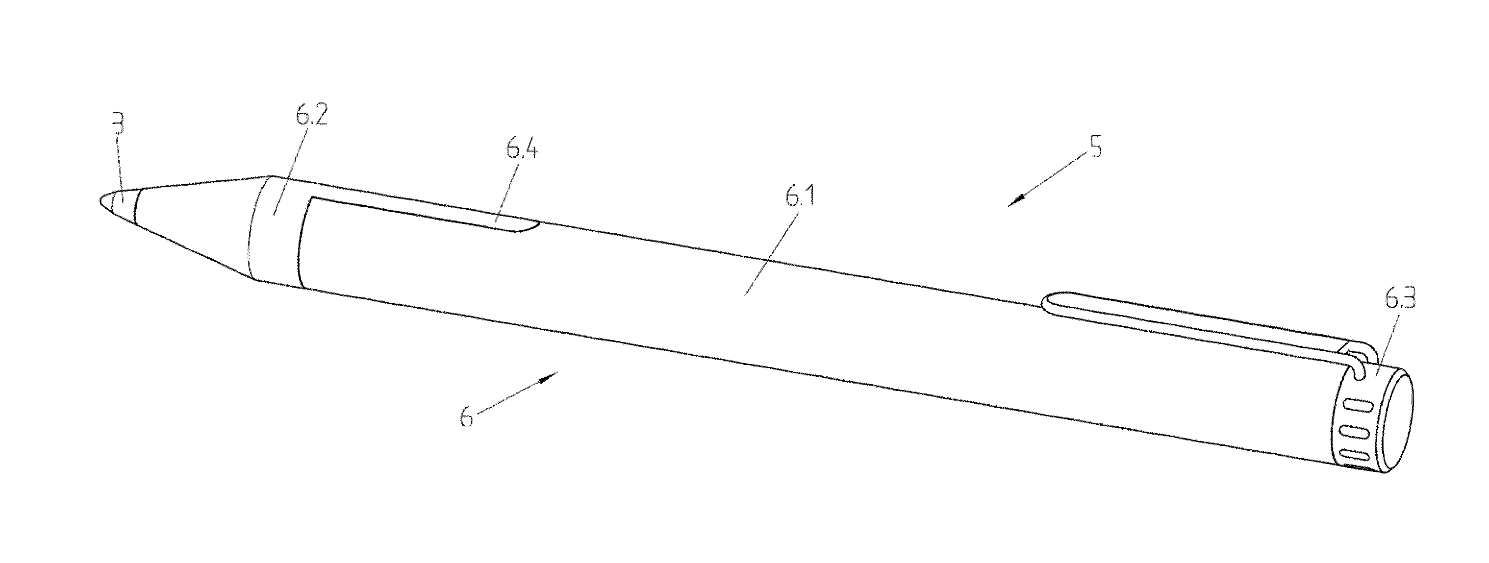
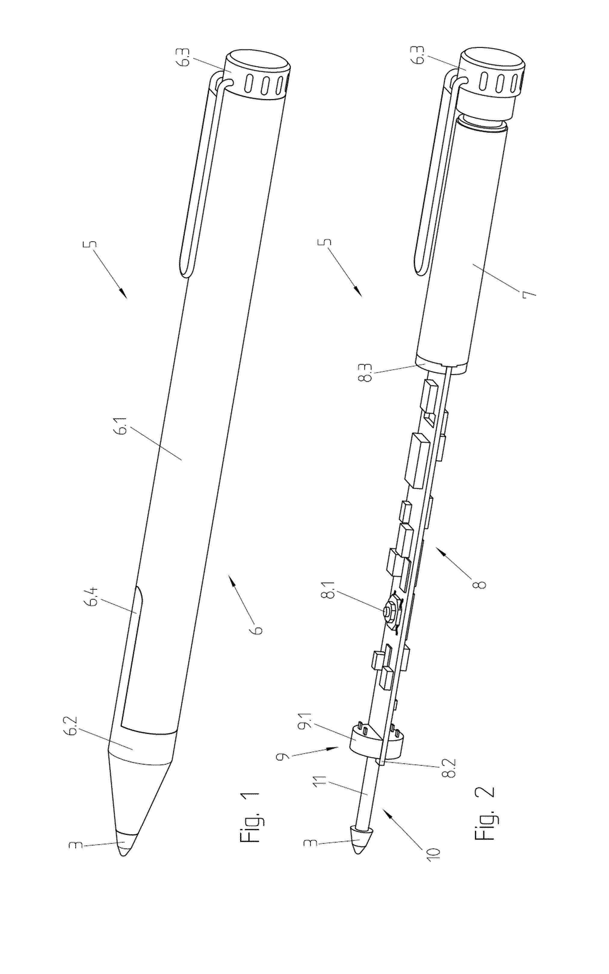
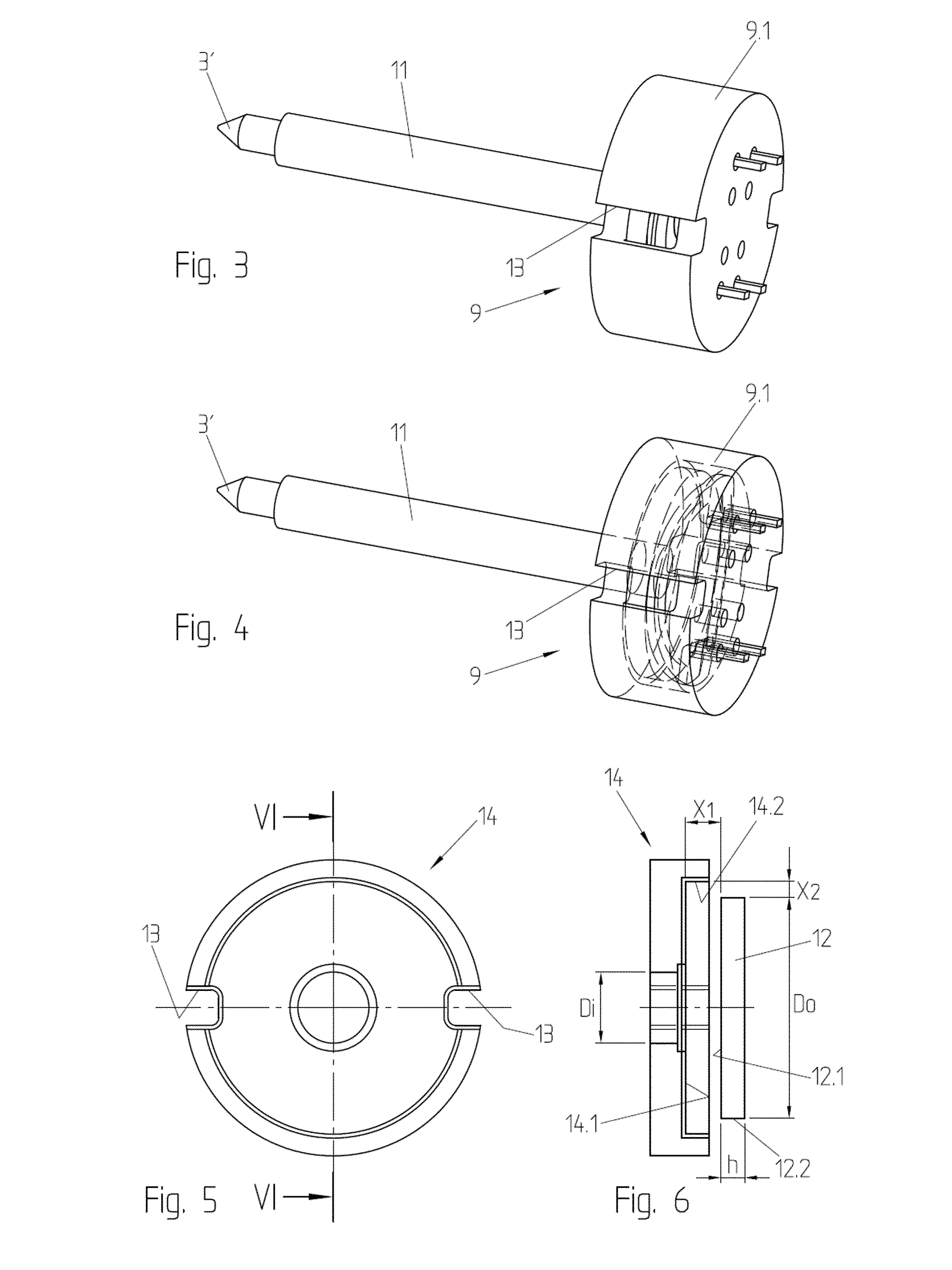
[0037]FIGS. 1 to 13 show an embodiment of an active pen 5. Everything disclosed with the following active pen is applicable for all other types of active position indicators.

[0038]The active pen 5 comprises a pen housing 6, a battery 7, a printed circuit board 8, a force sensor and a tip element 10 with a tip 3.

[0039]The pen housing 6 preferably encloses the battery 7, the printed circuit board 8 and a force detection mechanism 9 of the force sensor. The pen housing 6 preferably has an opening for comprising the tip element 10 such that the tip 3 is arranged outside of the housing 6 and connected via a rod 11 of the tip element 10 with the inner volume of the housing 6. Preferably the opening in the housing 6 guides the rod 11 of the tip element 10 such that the tip element 10 can (only) be moved in a displacement direction. However, it is also possible to detect the force in different directions. Preferably, the housing 6 has a cylindrical shape and the displacement direction is pa...


PUM


Abstract

Active position indicator comprising a movable tip element (10) configured to be displaced from an initial position in a displacement direction by a tip displacement depending on the force acting on a tip (3) arranged on a distal end of the tip element (10); a position signal circuit connected with said movable tip element (10) and configured to generate an indicator position signal to be applied on the tip (3); and a force sensor for detecting a force acting on the tip comprising a capacitive element with a capacitance value depending on the tip displacement for generating an electric feedback signal indicating the tip displacement; wherein the capacitive element comprises a capacitor distance depending on the tip displacement and a capacitor surface depending on the tip displacement.

Description

FIELD OF THE INVENTION[0001]The present invention concerns an active position indicator, in particular active pens, with a pressure sensor.DESCRIPTION OF RELATED ART[0002]Touch devices are used in various application fields in which object presence detections are involved, such as, but not limited to, touch pads, touch panels, touch screens or projective capacitive displays. Touch devices detect passive objects touching the touch device and can determine the position of the touch. This allows for example a user control. Unfortunately, the quality of the position detection of touches reduces with the size of the touched surface. Therefore, the quality of the position detection of a tip of a pen can only detected with a high detection error. Therefore, active position indicators, like active pens, contain electric circuits supporting a touch device to detect the position of the active position indicator with a lower error. This could be for example achieved by a capacitive or inductiv...

Claims


Application Information

Patent Timeline
Patent Type & Authority Applications(United States)
IPC IPC(8): G06F3/038G06F3/044G06F3/01G06F3/0354
CPCG01D5/2417G06F3/03545G06F3/044G06F3/0383G06F3/016
Inventor BALLAN, HUSSEINCELLA, PAOLOCARRARD, JEAN-DANIELPASTRE, MARCREIMANN, TRISTAN
Owner ADVANCED SILICON
Learn More