Wide operating temperature range electrophoretic device

a wide-range, electrophoretic technology, applied in the direction of door/window protective devices, instruments, constructions, etc., can solve the problems of increasing the haze of the electrophoretic device, the inability of the suspension fluid to dissolve/solubilize or swell the polymer elements within, and the inability of the suspension fluid to absorb the haze, etc., to achieve the effect of minimizing or avoiding the content of the aromatic fluid

Active Publication Date: 2016-08-25
E INK CORPORATION
View PDF0 Cites 11 Cited by
  • Summary
  • Abstract
  • Description
  • Claims
  • Application Information

AI Technical Summary

Benefits of technology

[0030]In embodiments the aromatic (i.e. aryl) content of said non-planar, solid polymer and said suspending fluid pair is minimized in order to maximize said Abbe number for each material.
[0031]In embodiments said aromatic con

Problems solved by technology

In general, the prior art of smart glass and outdoor displays does not describe what happens this solar energy when it is absorbed by light states, and is largely silent with respect to operating at elevated temperature due to heat build-up within a device that absorbs incident solar energy.
The problems an electrophoretic device encounters due to use at elevated temperature include significantly increased haze with respect to a normative (i.e. reference) ambient temperature, and significantly increased ability of the suspending fluid to dissolve/solubilize or swell polymer elements within the electrophoretic cell and in contact with the fluid (e.g., non-planar polymer structures and charged particles).
(the refractive index reference temperature) can develop a perceivable increase in haze from about 30 degrees C. and go on to become cloudy or translucent at about 70 degrees C. The polymer dissolution or swelling problem develops over time and using prior art devices/methods results in device failure over days or months depending on material selection and the total number of hours at elevated temperature.
Furthermore, unless measures are taken to manage heat build-up in very hot

Method used


Image

  • Wide operating temperature range electrophoretic device
  • Wide operating temperature range electrophoretic device
  • Wide operating temperature range electrophoretic device

Examples


Embodiment Construction

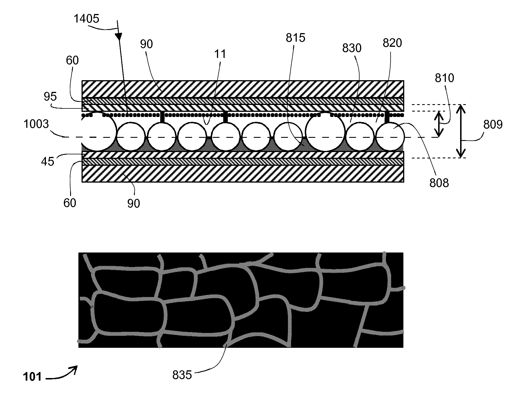
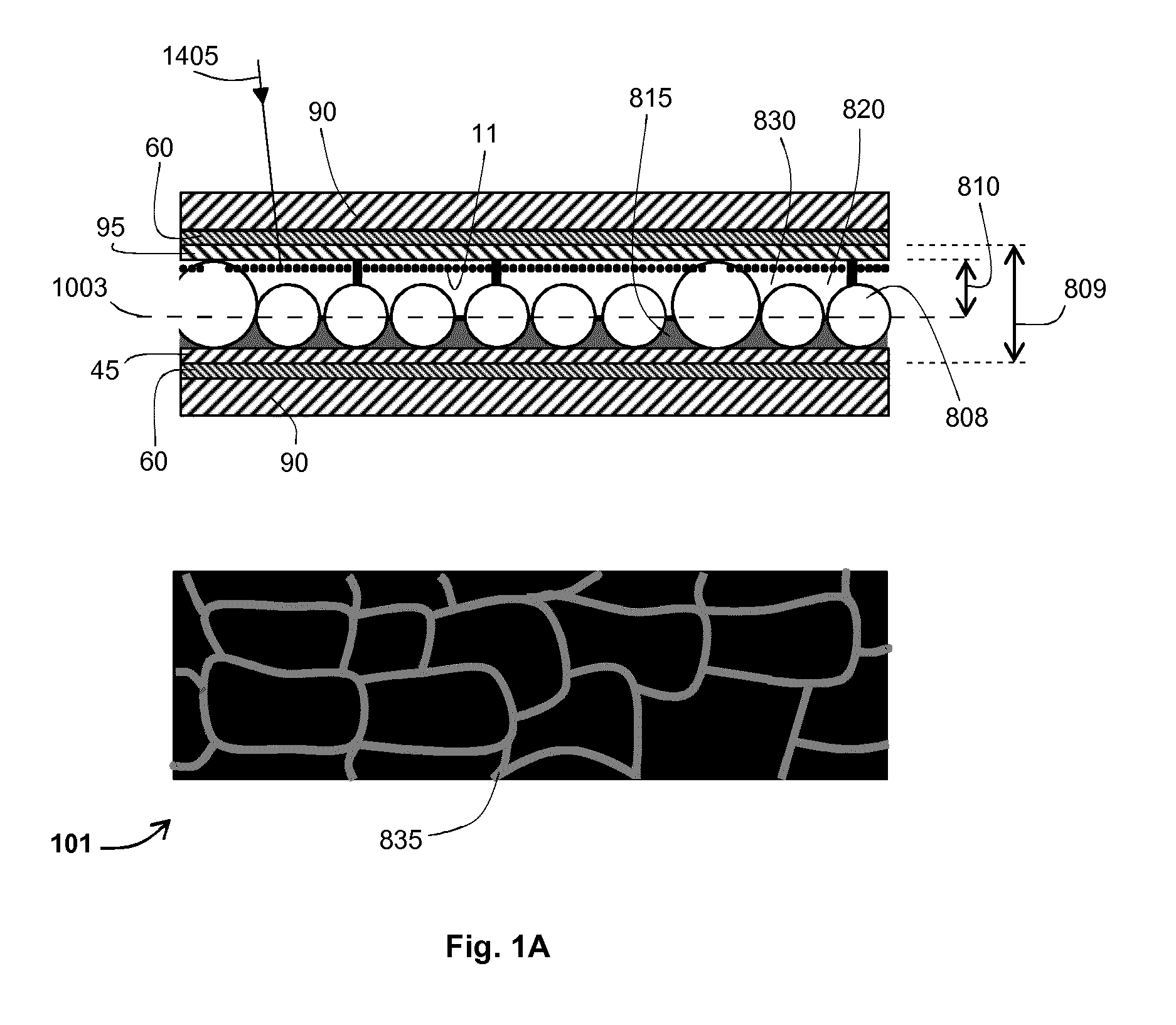
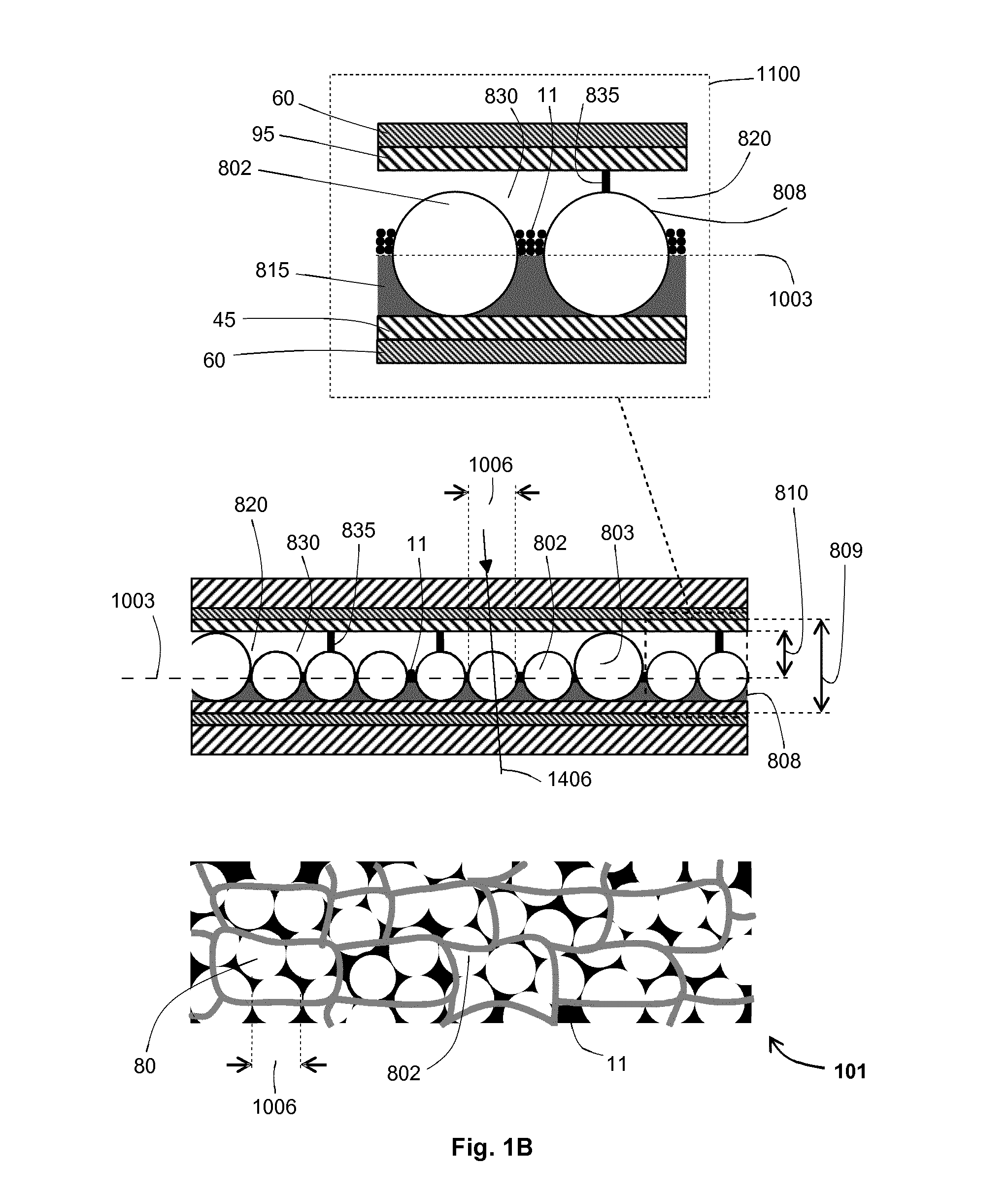
[0080]The present invention provides an electrophoretic device whose electrophoretic cell has one or more transparent light states. The device has a wide operating temperature range suitable for many of the climates found in highly populated parts of the world. Advantageously, the device is suitable for applications that are exposed to outdoor temperatures and to sunlight.

[0081]In a first aspect the refractive index of non-planar, solid polymer elements within the electrophoretic cell are refractive index matched to the suspending fluid over half or more of the operating temperature range by matching the thermo-optic coefficient (i.e. the temperature coefficient of refractive index per Kelvin also known as the differential of refractive index with respect to temperature do / dT) of the solid polymer to the optically-transparent fluid's coefficient. This is achieved using optically-transparent, elastomeric, solid polymer.

[0082]In another aspect the chromatic dispersion of non-planar, s...


PUM


Abstract

An electrophoretic device (101) comprises a first electrode (60) and a second electrode (60) spaced apart from the first electrode (60). An electrophoretic cell (809) containing an electrophoretic ink (830) and one or more optically-transparent, non-planar, solid polymer elements (808) is located between the electrodes (60). The ink (830) includes charged particles (11) of at least one type suspended in an optically-transparent suspending fluid (820). The refractive indices of the solid polymer elements (808) and the suspending fluid (820) are matched to have a difference of less than 0.0075, and for half or more of the operating temperature range of the device (0° C.-70° C.), the thermo-optic coefficients (temperature coefficient of refractive index per Kelvin) of the solid polymer elements (808) and the suspending fluid (820) are matched to have an arithmetic-mean difference of less than 0.0002/K in magnitude.

Description

RELATED APPLICATIONS[0001]The present application relates to Irish Patent Application No. S2013 / 0104 titled “An Electrophoretic Device Having a Transparent Light State” filed on 22 Mar. 2013 (attorney reference P106878IE00).FIELD[0002]The present invention relates to an electrophoretic device for use over a wide operating temperature range.BACKGROUND TO THE INVENTION[0003]There is a need for an electro-optical device that in one or more light states is transparent to visible light and in other light states attenuates light. Applications for such a device include use as a light attenuator in a smart glass, use as a see-through display, or use as a sunlight-readable, reflective display. By controlling light transmittance in windows, glass facades or roof systems, functions including see-through (i.e. transparent), privacy (opaque), electronically-variable tinting or dimming, or black-out can be provided. In display devices functionality can be extended into new areas such as providing...

Claims


Application Information

Patent Timeline
IPC IPC(8): G02F1/167E06B9/24G02F1/1675
CPCG02F1/167E06B2009/2464E06B9/24G02F2001/1678G02F1/1675
Inventor O'KEEFFE, DONAL
Owner E INK CORPORATION
Why Eureka
Try Eureka