Compression Conveying Mechanism for Bagged Spring Production

a conveying mechanism and production machine technology, applied in mechanical conveyors, packaging, transportation and packaging, etc., can solve the problems of inability to convey, low efficiency, and complicated whole structure design of the bagged spring production machine, and achieve high automation degree, high production efficiency, and simple structure

Active Publication Date: 2016-09-01
GUANGZHOU LIANROU MACHINERY & EQUIP
View PDF0 Cites 5 Cited by
  • Summary
  • Abstract
  • Description
  • Claims
  • Application Information

AI Technical Summary

Benefits of technology

[0007]The compression conveying mechanism for bagged spring production mainly automatically compresses the spring produced by the spring coiling mechanism and conveys the spring to a subsequent working procedure to package the spring in a cloth bag; by providing the spring conveying mechanism and the spring compression conveying mechanism, after the spring is conveyed between the two baffles by the spring conveying mechanism, the spring moves from the end where the distance between the two baffles is large to the other end where the distance between the two baffles is small; with the gradually decreased distance between the two baffles, the two ends of the spring are gradually squeezed by the conveying belts outside the two baffles and thus compressed, after the spring is compressed to a certain degree, the spring is disengaged from the spring conveying mechanism automatically and conveyed to the subsequent working procedure to package the spring in a cloth bag through the spring compression conveying mechanism, which abandons the structural form of a traditional bagged spring production machine, so that the present invention has the advantages of high automation degree, simple structure, high production efficiency, and more stable compression and conveying.

Problems solved by technology

At present, in the bagged spring production machine, it is desirable to specially design a spring feed mechanism and a spring compression mechanism to flatten the spring, and then the flattened spring is pushed into the cloth bag for packaging, wherein the present bagged spring production machine has the defects of complicated entire structural design, huge volume, instable conveying and low efficiency, and is difficult to satisfy the requirements of automation and large-scale mass production.

Method used


Image

  • Compression Conveying Mechanism for Bagged Spring Production
  • Compression Conveying Mechanism for Bagged Spring Production
  • Compression Conveying Mechanism for Bagged Spring Production

Examples


Embodiment Construction

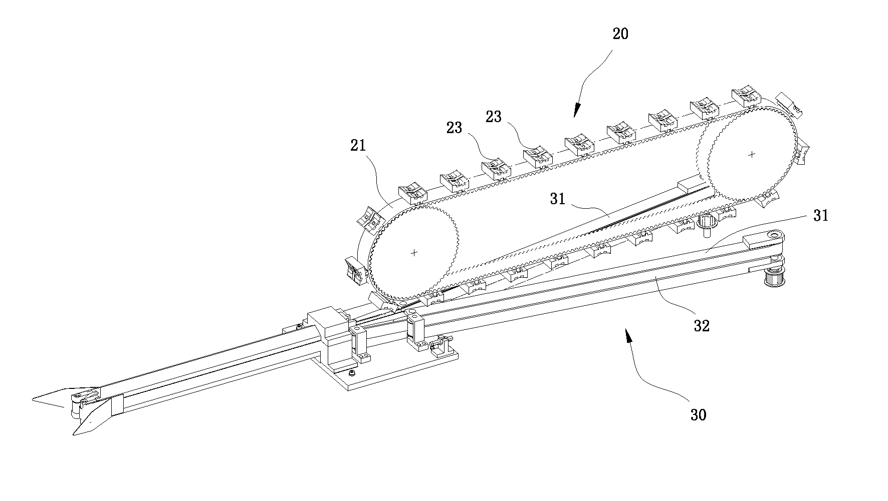
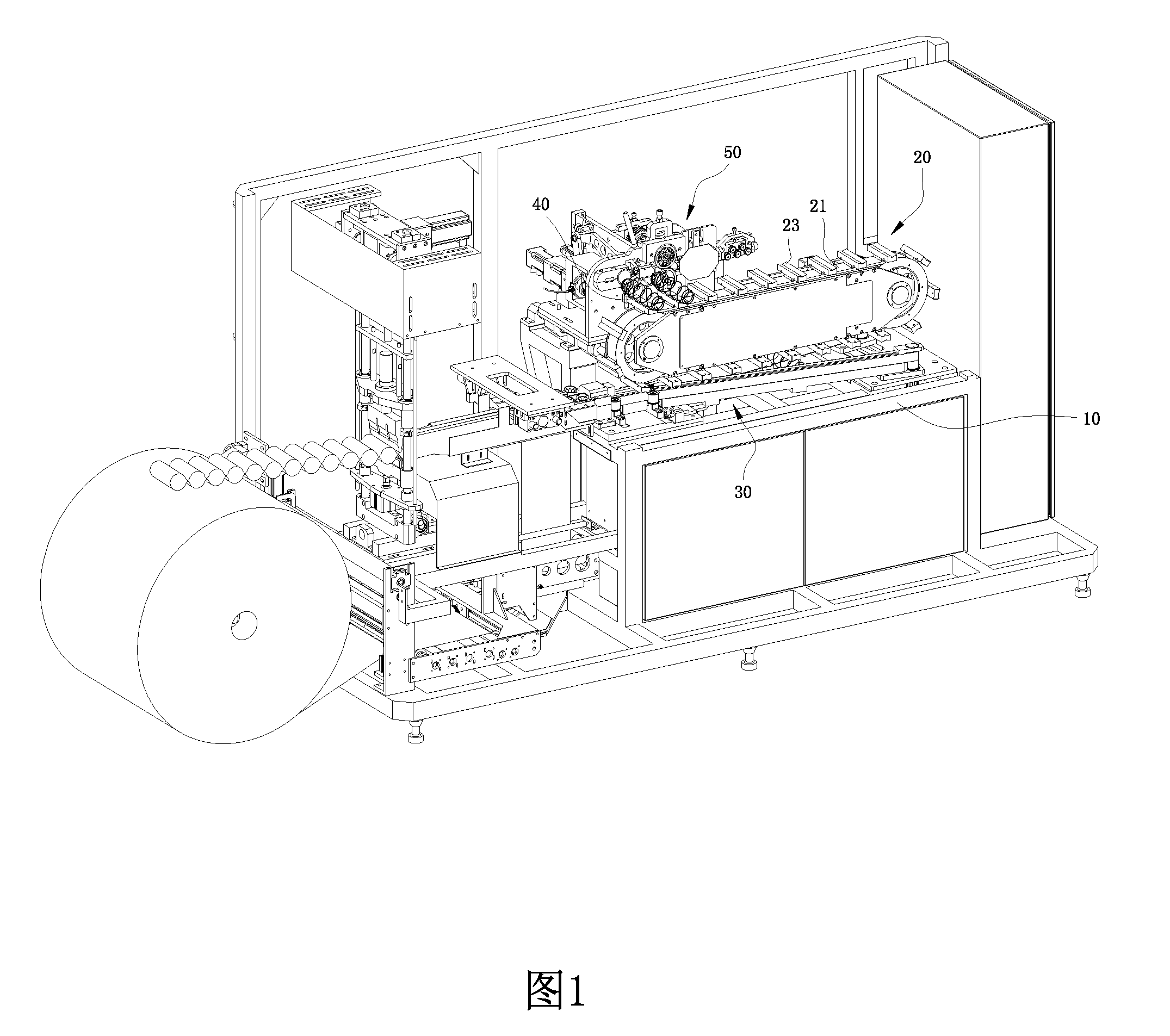
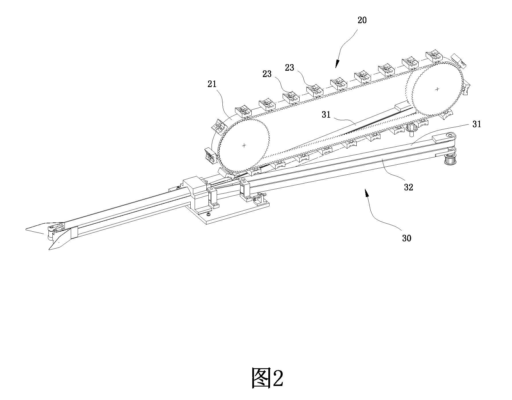
[0011]Referring to FIG. 1 and FIG. 2, a compression conveying mechanism for bagged spring production includes a machine frame 10, a spring conveying mechanism 20, and a spring compression conveying mechanism 30. The spring compression conveying mechanism 30 bears a spring 40 conveyed by the spring conveying mechanism 20 and compresses the spring, the spring compression conveying mechanism 30 includes two baffles 31 disposed on the machine frame 10 and conveying belts 32 wound on the outsides of the baffles 31, and the distance between the two baffles 31 is gradually decreased from one end to the other end. The spring conveying mechanism 20 conveys the spring 40 to a position between the two baffles 31 and drives the spring 40 to move so that the spring 40 can be moved from the end where the distance between the two baffles 31 is large to the other end where the distance between the two baffles 31 is small. The spring 40 is gradually compressed in the horizontal moving process along ...


PUM


Abstract

Disclosed is a compression conveying mechanism for bagged spring production. The mechanism comprises a machine frame (10), a spring conveying mechanism (20), and a spring compression conveying mechanism (30). The spring compression conveying mechanism (30) comprises two baffles (31) disposed on the machine frame and conveying belts (32) wound on the outsides of the baffles (31), and the distance between the two baffles (31) is gradually decreased from one end to the other end. The spring conveying mechanism (20) conveys a spring to a position between the two baffles (31) and drives the spring to move so that the spring can be moved from the end where the distance between the two baffles (31) is large to the other end where the distance between the two baffles (31) is small. The spring is gradually compressed in the horizontal moving process along with the gradually decreased distance between the two baffles (31), and after the spring is compressed to a certain degree, the spring is disengaged from the spring conveying mechanism (20) and is conveyed by the spring compression conveying mechanism (30). By providing the spring conveying mechanism (20) and the spring compression conveying mechanism (30), compression and conveying of a spring are integrated, a structural form of a traditional bagged spring production machine is abandoned, the degree of automation is high, the structure is simple, the production efficiency is high, and compression and conveying are more stable.

Description

FIELD OF THE INVENTION[0001]The present invention relates to the technical field of bagged spring production devices, and more particularly, to a compression conveying mechanism for a bagged spring production machine.BACKGROUND OF THE INVENTION[0002]A bagged spring production machine is used for gradually packaging single independent spring into a cloth bag. At present, in the bagged spring production machine, it is desirable to specially design a spring feed mechanism and a spring compression mechanism to flatten the spring, and then the flattened spring is pushed into the cloth bag for packaging, wherein the present bagged spring production machine has the defects of complicated entire structural design, huge volume, instable conveying and low efficiency, and is difficult to satisfy the requirements of automation and large-scale mass production.SUMMARY OF THE INVENTION[0003]A technical problem to be solved by the present invention is to provide a compression conveying mechanism fo...

Claims


Application Information

Patent Timeline
Patent Type & Authority Applications(United States)
IPC IPC(8): B65G15/14B65G17/46B65G37/00B65G17/12
CPCB65G15/14B65G37/00B65G17/46B65G17/12B65G15/58B65B25/00B65B35/243B65B63/026
Inventor TAN, ZHIMING
Owner GUANGZHOU LIANROU MACHINERY & EQUIP
Why Eureka
Try Eureka