
Combustion state estimation method

Active Publication Date: 2016-09-01
TOYOTA JIDOSHA KK
View PDF3 Cites 2 Cited by
  • Summary
  • Abstract
  • Description
  • Claims
  • Application Information

AI Technical Summary

Benefits of technology

The invention provides a method to efficiently estimate the time it takes for an internal combustion engine to catch fire after it has been started. This method allows for quick and accurate estimations of the timing of maximum heat release rate, even when the valve opening characteristics of the engine change. This means that the method can quickly and easily determine the time it takes for the engine to catch fire at different engine speeds and valve settings. This is important information for engine designers and can improve the efficiency and performance of their engines.

Problems solved by technology

In addition, when the first combustion period length is acquired with actual measurement, an enormous amount of experiments need to be carried out for various engine operating states each time the valve opening characteristic of the intake valve is changed.
That is, it is required to expend extremely large amounts of time and effort in order to accurately acquire a first combustion period length for each of various valve opening characteristics of the intake valve.

Method used


Image

  • Combustion state estimation method
  • Combustion state estimation method
  • Combustion state estimation method

Examples


first application example

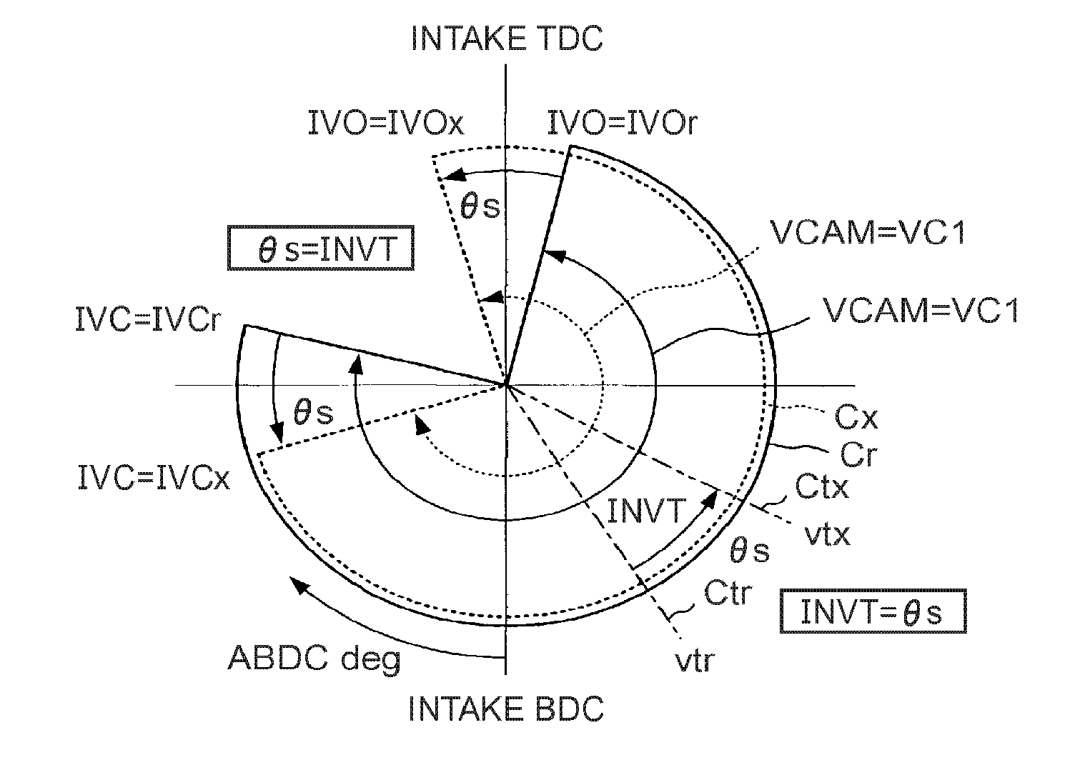
[0200]For example, the above-described mathematical expression (3) and the findings 1 (the above-described mathematical expression (1A) or mathematical expression (1B)) of the embodiment method are also used in the routine shown by the flowchart in

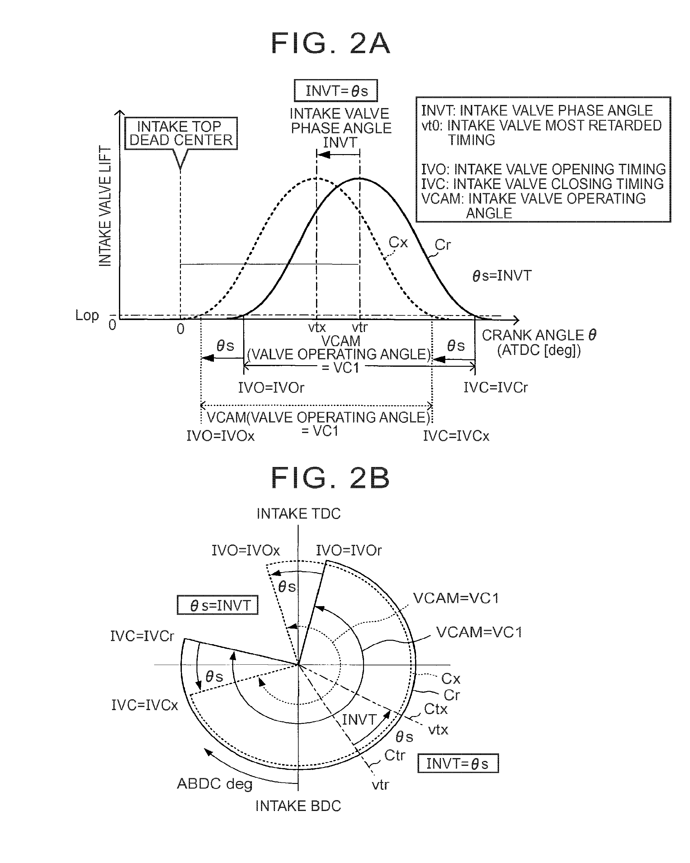
[0201]FIG. 35. This routine is used instead of the routine shown in FIG. 15 when the intake valve phase angle INVT is a specific phase angle INVTx and the intake valve operating angle VCAM is the reference valve operating angle VCAMr (that is, when the valve opening characteristic of each intake valve is a specific characteristic that differs from the reference characteristic in only the intake valve phase angle INVT). Hereinafter, this routine will be simply described. Like step numbers denote the steps shown in FIG. 35 and also shown in FIG. 15, and the description of those steps is omitted. The CPU receives the specific phase angle INVTx in step 1505.

[0202]When the CPU calculates the combustion chamber volume V@θzdQpeak at the virtual m...

second application example

[0209]For example, the above-described mathematical expression (3) and the findings 2 (the above-described mathematical expression (2A) or mathematical expression (2B)) of the embodiment method are also used in the routine shown by the flowchart in FIG. 36. This routine is used instead of the routine shown in FIG. 15 when the intake valve operating angle VCAM is the specific operating angle VCAMx and the intake valve closing timing IVC is the reference valve closing timing IVCr (that is, when the valve opening characteristic of each intake valve is a specific characteristic that differs from the reference characteristic in only the intake valve operating angle VCAM). Hereinafter, this routine will be simply described. Like step numbers denote the steps shown in FIG. 36 and also shown in FIG. 15, and the description of those steps is omitted. The CPU receives the specific valve operating angle VCAMx in step 1505.

[0210]When the CPU calculates the combustion chamber volume V@θzdQpeak a...


PUM


Abstract

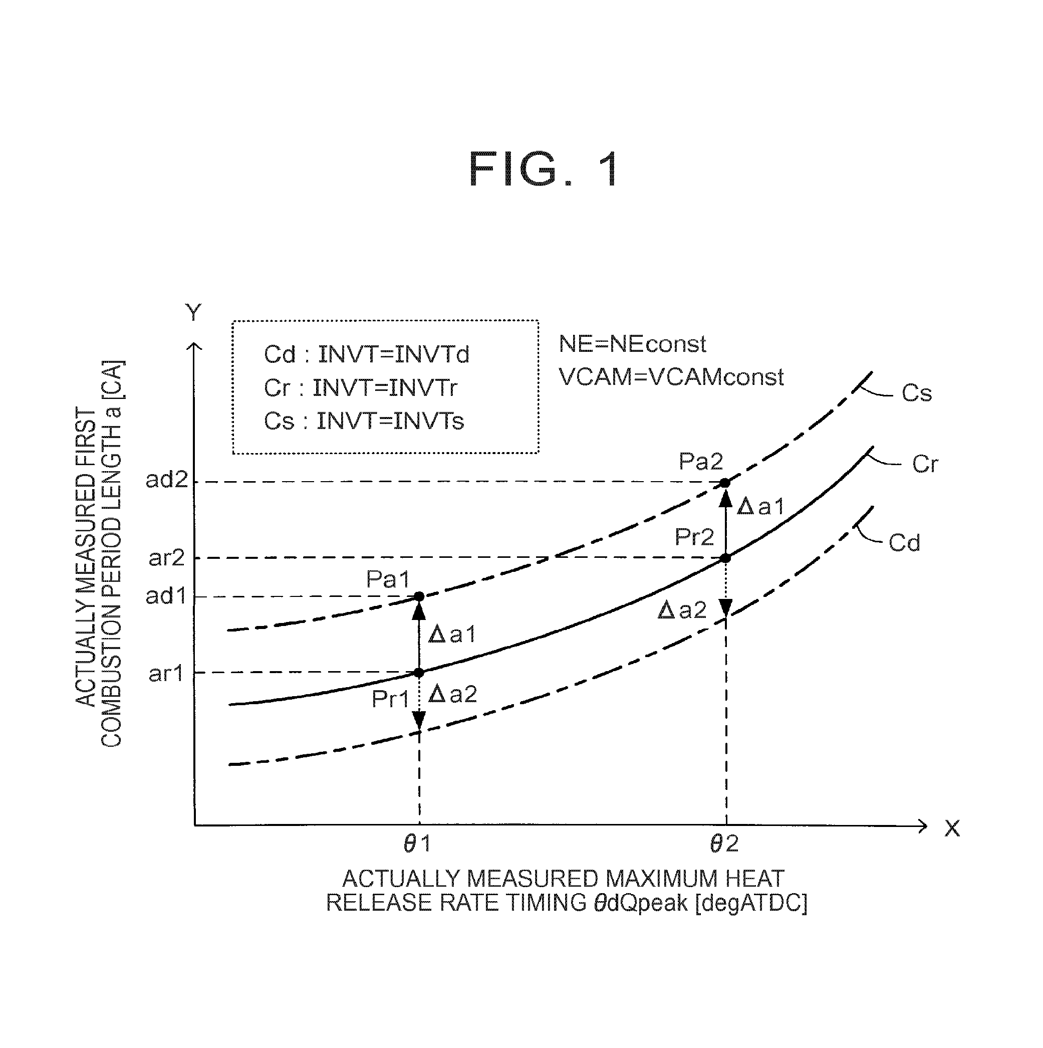
Where a relationship between maximum heat release rate timing and a first combustion period length (that is, a reference relationship) in the case where an engine rotation speed of a spark-ignition internal combustion engine is a selected speed and a valve opening characteristic of an intake valve is a reference characteristic is expressed by the function are f=f(θdQpeak) where θdQpeak denotes the maximum heat release rate timing and aref denotes the first combustion period length, when the valve opening characteristic of the intake valve changes to a specific characteristic from this state, a first combustion period length for selected maximum heat release rate timing is estimated on the basis of the mathematical expression a=f(θ2)+Δa1 where θ2 denotes the selected maximum heat release rate timing and a denotes the first combustion period length.

Description

INCORPORATION BY REFERENCE[0001]The disclosure of Japanese Patent Application No. 2015-037160 filed on Feb. 26, 2015 including the specification, drawings and abstract is incorporated herein by reference in its entirety.BACKGROUND OF THE INVENTION[0002]1. Field of the Invention[0003]The invention relates to a combustion state estimation method that estimate the length of a first combustion period (first combustion period length) regarding combustion of fuel in an internal combustion engine as one of parameters that indicate a combustion state.[0004]2. Description of Related Art[0005]Various techniques for estimating changes in the amount (heat release amount, heat generation amount) Q of heat that is generated as a result of combustion of fuel in a combustion chamber have been suggested in order to estimate a combustion state of fuel in an internal combustion engine. Particularly, changes in heat release rate (dQ / dθ) in a crank angle (that is, a heat release rate waveform) are impor...

Claims


Application Information

Patent Timeline
IPC IPC(8): F02B5/02G01N25/22
CPCG01N25/22F02B5/02F02D37/00F02D35/028F02D2041/001F02D2041/1412F02D2041/1433
Inventor IMAEDA, MUNENORI
Owner TOYOTA JIDOSHA KK
Learn More