Hybrid vehicle, controller for a variable valve timing (lift and/or angle) device for the combustion engine of the hybrid vehicle, and control method for such hybrid vehicle

a hybrid vehicle and controller technology, applied in the direction of engine starters, machines/engines, output power, etc., can solve the problems of user experience of vibration and noise resulting from the start-up of the internal combustion engin

Inactive Publication Date: 2016-09-01
TOYOTA JIDOSHA KK
View PDF3 Cites 9 Cited by
  • Summary
  • Abstract
  • Description
  • Claims
  • Application Information

AI Technical Summary

Benefits of technology

[0034]According to the disclosure, it is possible to control the operation characteristic of the intake valve at start-u

Problems solved by technology

Therefore, vibrations and noise resulting from start-up of th

Method used


Image

  • Hybrid vehicle, controller for a variable valve timing (lift and/or angle) device for the combustion engine of the hybrid vehicle, and control method for such hybrid vehicle
  • Hybrid vehicle, controller for a variable valve timing (lift and/or angle) device for the combustion engine of the hybrid vehicle, and control method for such hybrid vehicle
  • Hybrid vehicle, controller for a variable valve timing (lift and/or angle) device for the combustion engine of the hybrid vehicle, and control method for such hybrid vehicle

Examples


first embodiment

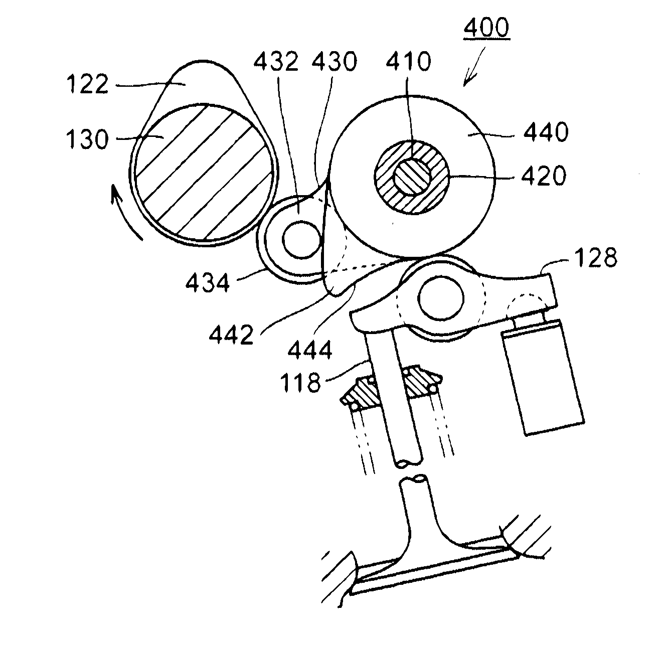
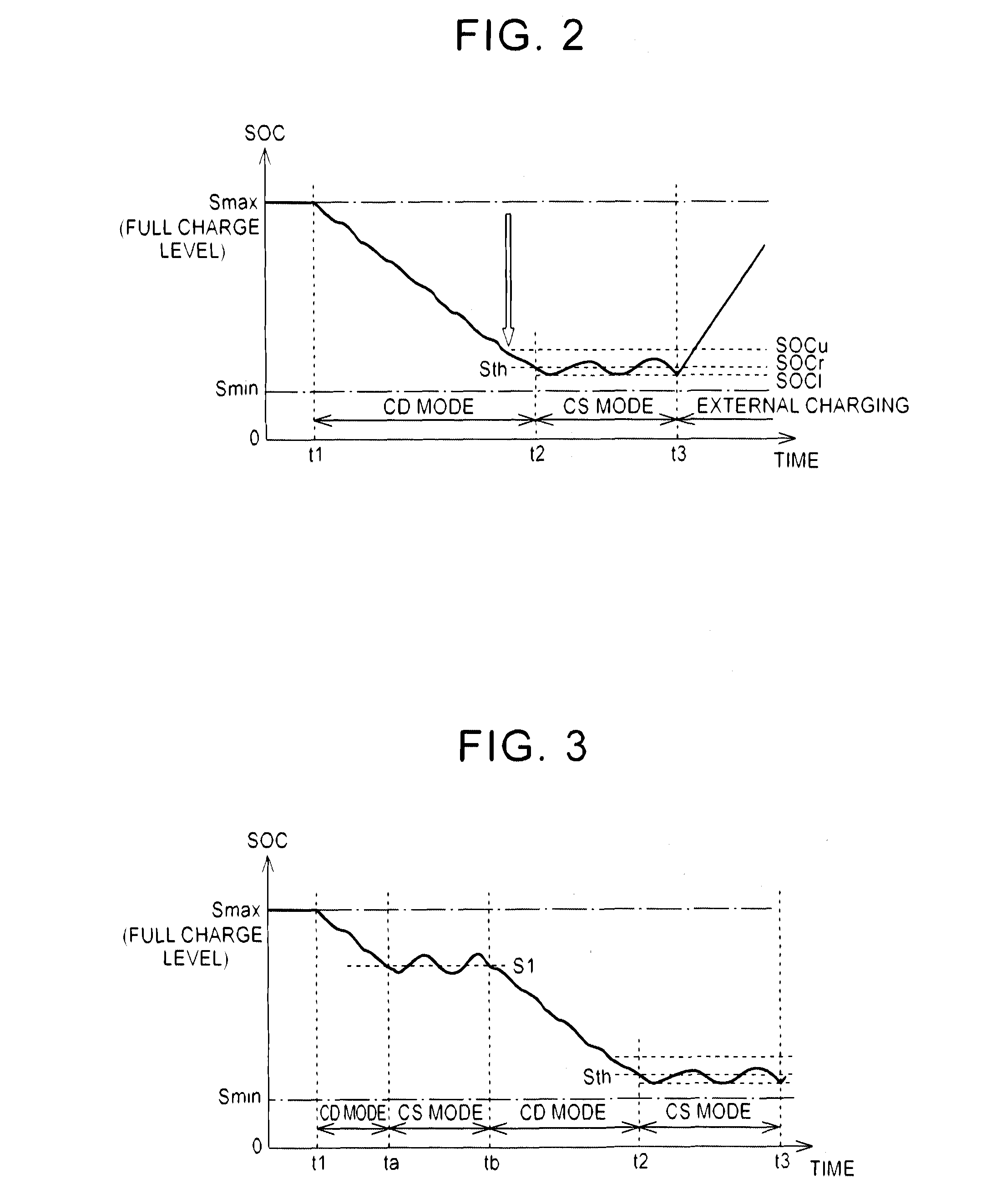
[0153]Therefore, in the first embodiment, the operation characteristic of each intake valve 118 at engine start-up is appropriately controlled in correspondence with a selected one of the CS mode and the CD mode.

[0154]As shown in FIG. 14, in the first embodiment, when the CS mode in which the frequency of start-up of the engine 100 is high is selected, the operation characteristic of each intake valve 118 at start-up of the engine 100 is controlled by giving a higher priority to vibration suppression at engine start-up.

[0155]In contrast, when the CD mode in which the frequency of start-up of the engine is relatively low is selected, the operation characteristic of each intake valve 118 is controlled such that the valve lift and valve operating angle of each intake valve 118 at engine start-up are smaller than the valve lift and valve operating angle of each intake valve 118 in the CS mode. That is, the operation characteristic of each intake valve 118 is controlled by giving a highe...

second embodiment

[0184]FIG. 18 is a flowchart that illustrates the control structure of intake valve control in the hybrid vehicle according to the The control process shown in FIG. 18 may be executed by the controller 200.

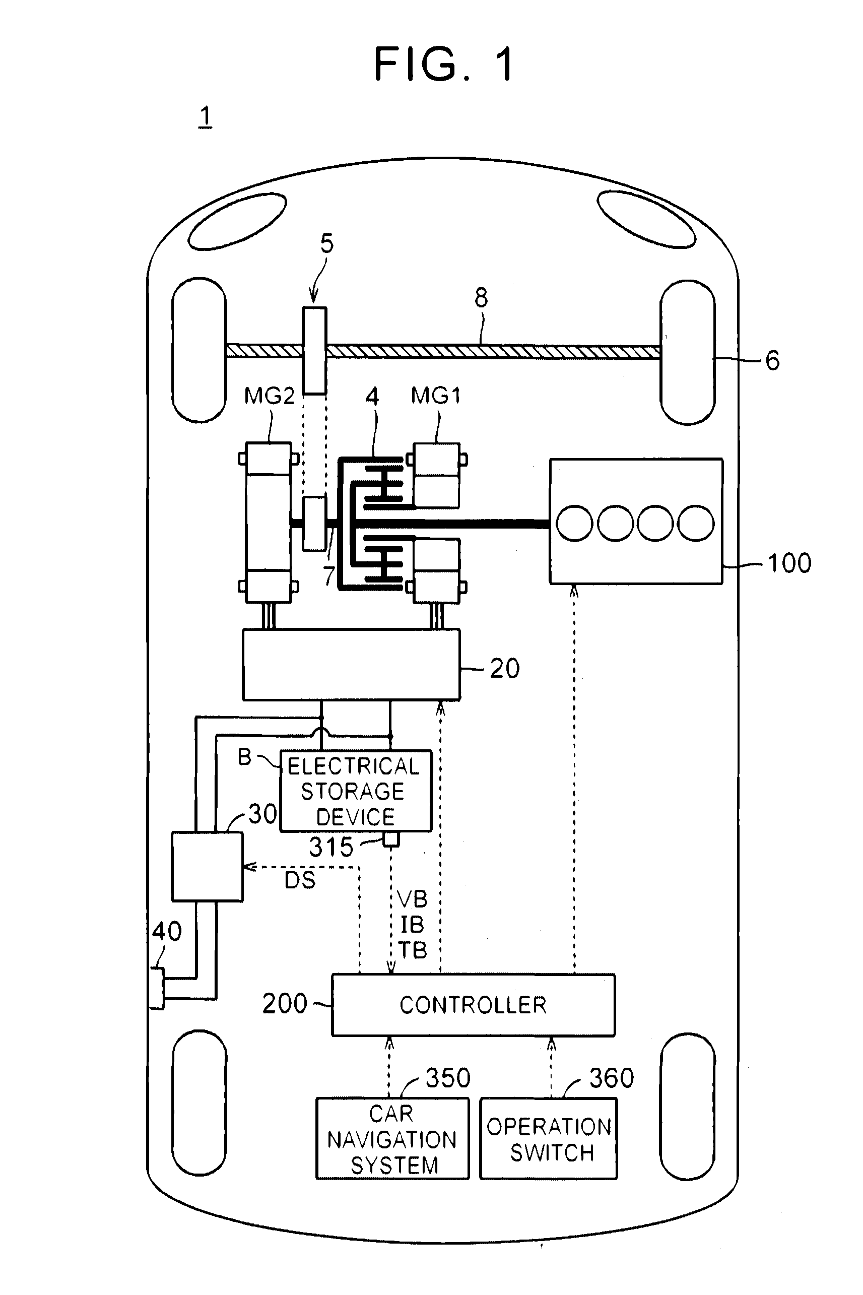
[0185]As shown in FIG. 18, the controller 200 executes the processes from step S210 during engine stop, that is, when affirmative determination is made in step S200. During engine stop (when affirmative determination is made in S200), the controller 200 determines whether the engine start-up condition is satisfied (S210). For example, as described with reference to FIG. 5, when the output parameter Pr (total required power Ptl) increases above the predetermined threshold, the engine start-up command is issued in response to the fact that the engine start-up condition is satisfied. When the engine start-up condition is not satisfied (when negative determination is made in S210), no engine start-up command is issued, and the stopped state of the engine 100 is continued.

[0186]When t...


PUM


Abstract

A hybrid vehicle includes a rotary electric machine, an internal combustion engine, and a controller. The rotary electric machine generates driving force for the hybrid vehicle. The internal combustion engine includes a variable valve actuating device configured to change an operation characteristic of an intake valve. The controller controls travel of the vehicle by selectively applying one of a first driving mode and a second driving mode. The controller controls the variable valve actuating device such that at least one of a valve lift of the intake valve and a valve operating angle of the intake valve at start-up of the internal combustion engine when the first driving mode is selected is smaller than the corresponding at least one of the valve lift of the intake valve and the valve operating angle of the intake valve at start-up of the internal combustion engine when the second driving mode is selected.

Description

BACKGROUND[0001]1. Field[0002]The disclosure relates to a hybrid vehicle, a controller for a hybrid vehicle, and a control method for a hybrid vehicle and, more particularly, to a hybrid vehicle that includes an internal combustion engine including a variable valve actuating device for changing the operation characteristic of an intake valve, a controller for the hybrid vehicle, and a control method for the hybrid vehicle.[0003]2. Description of Related Art[0004]There is known an internal combustion engine including a variable valve actuating device that is able to change the operation characteristic of an intake valve. There is also known a variable valve actuating device that is able to change at least one of the valve lift and valve operating angle of an intake valve as such a variable valve actuating device (see Japanese Patent Application Publication No. 2005-299594 (JP 2005-299594 A), Japanese Patent Application Publication No. 2004-183610 (JP 2004-183610 A), Japanese Patent A...

Claims


Application Information

Patent Timeline
IPC IPC(8): F02N19/00B60W10/08B60K6/24B60W20/13B60K6/44B60K6/46F02D13/02B60W10/06B60L50/16
CPCF02N19/004F02D13/0223B60W10/08B60W10/06B60W20/13B60K6/44B60Y2300/437B60K6/24B60W2710/0605B60W2710/08Y10S903/93Y10S903/905B60Y2200/92B60K6/46B60K6/445B60W2030/206B60W2710/0633B60W20/40F02N11/0814F02N2200/023F02N2200/046F02N2200/0801F02N2200/101F02N2300/2002F01L13/0063Y02T10/12Y02T10/62B60W20/00B60K6/20B60W30/192
Inventor TERAYA, RYUTAASAMI, YOSHIKAZUKATO, TOSHIKAZU
Owner TOYOTA JIDOSHA KK
Why Eureka
Try Eureka