Device and method for checking a switching operation of an electric switch

Inactive Publication Date: 2016-09-01
OMICRON ELECTRONICS GMBH
View PDF10 Cites 1 Cited by
  • Summary
  • Abstract
  • Description
  • Claims
  • Application Information

AI Technical Summary

Benefits of technology

[0005]The object on which the invention is based therefore is to provide improved methods and devices for checking a switching operation of an electric switch, which in

Problems solved by technology

The attaching of the path or angle sensor in conventional devices and methods may prove to be relatively expensive and complicated.
T

Method used


Image

  • Device and method for checking a switching operation of an electric switch
  • Device and method for checking a switching operation of an electric switch
  • Device and method for checking a switching operation of an electric switch

Examples


Embodiment Construction

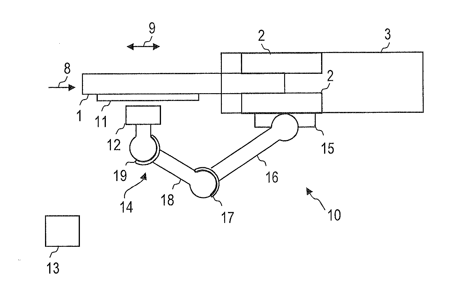
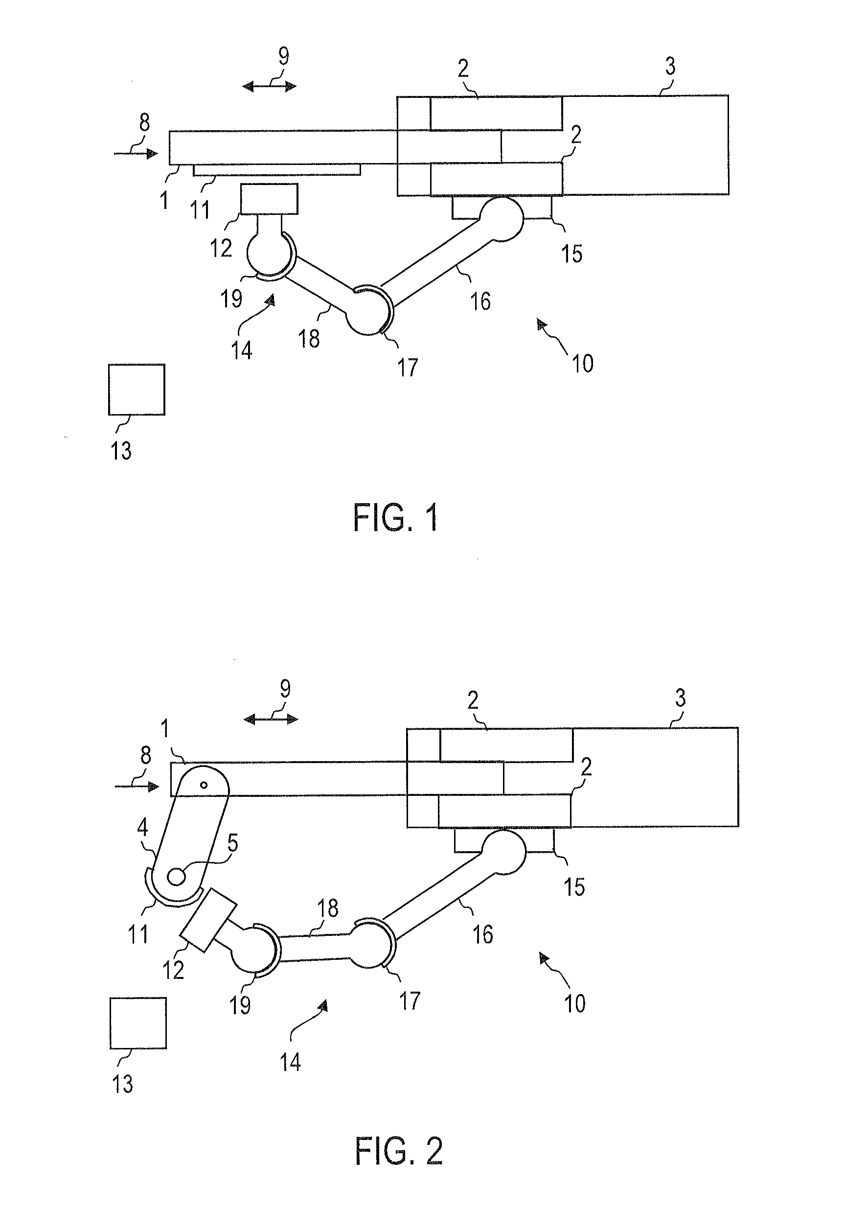
[0041]FIG. 1 shows a device 10 for checking a switching operation of an electric switch. The electric switch may be, for example, an electric extra-high-, high- or medium-voltage switch. The electric switch may comprise a switching chamber 3, in which fixed contacts 2 are arranged stationarily relative to the switching chamber 3. The fixed contacts 2 may, for example, be mechanically connected to the switching chamber 3. A movable switching element 1 of the electric switch can project through an opening of the switching chamber 3 into the switching chamber 3 in such a way that on a movement of the movable switching element 1 in a movement direction 8 an electrical contact between the fixed contacts 2 and the movable switching element 1 can be selectively made or broken.

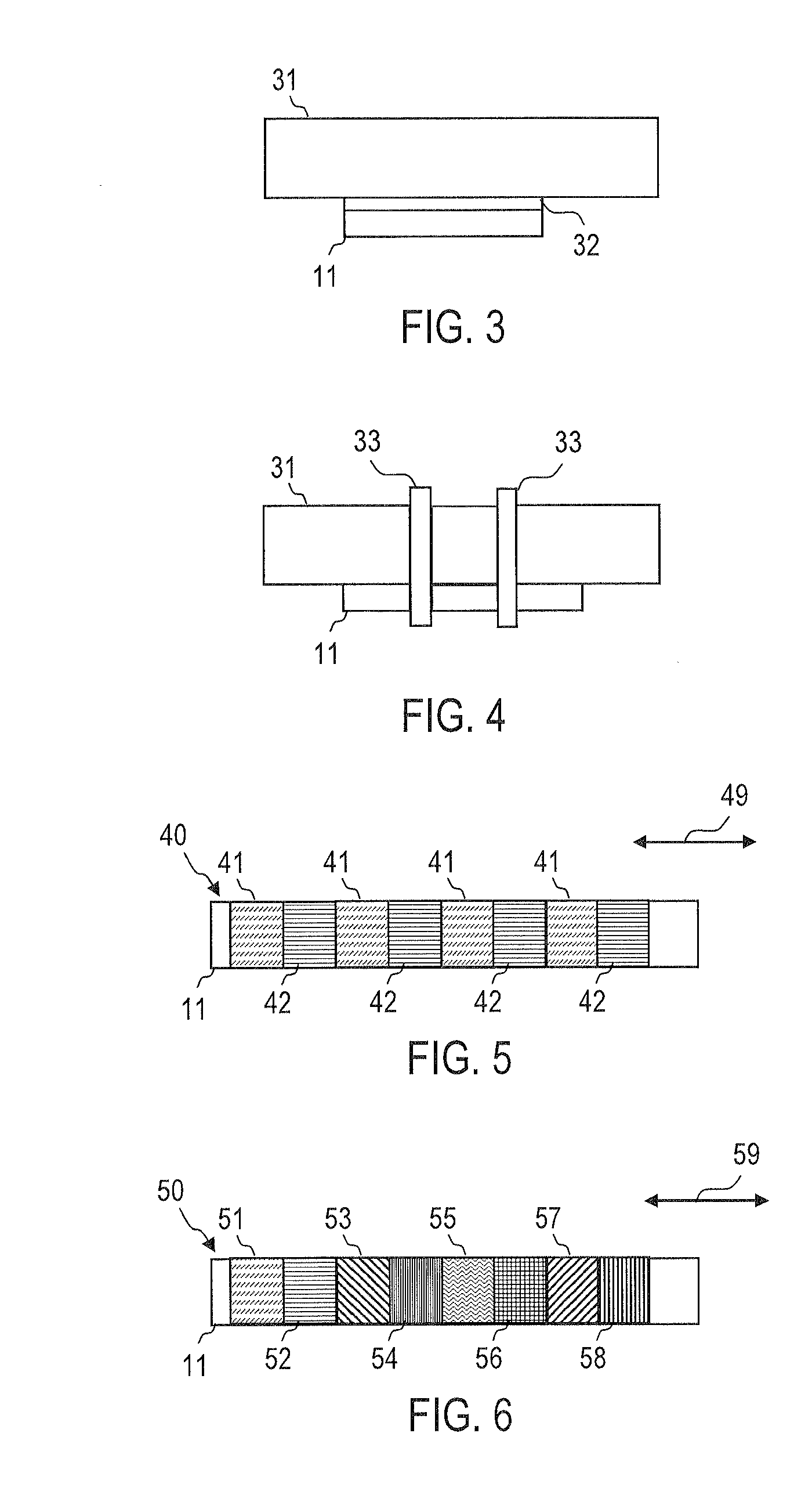
[0042]The device 10 serves for checking the correct functioning of the electric switch. The device 10 comprises a marking element 11 having a magnetization pattern comprising a plurality of magnetic markings. The plur...


PUM


Abstract

In order to check a switching operation of an electric switch (1-3), a movement of a movable switching element (1) of the electric switch (1-3) is sensed during the switching operation. For that purpose, a marking element (11) is used, the marking element (11) having a magnetization pattern comprising a plurality of magnetic markings. A path length (9) of a relative movement between the marking element (11) and a sensor (12) is determined.

Description

TECHNICAL FIELD OF THE INVENTION[0001]The invention relates to methods and devices for checking a switching operation of an electric switch. The invention relates in particular to methods and devices for checking opening and closing operations of electric extra-high-, high- or medium-voltage switches.BACKGROUND OF THE INVENTION[0002]Electric power switches and load switches, such as e.g. extra-high-, high- or medium-voltage switches, must be checked after a new installation, after a modification or on an inspection before they can be put into operation for the first time or again. An important check in this regard is the inclusion of a so-called path-time diagram. This makes it possible in particular to check whether the opening operation or closing operation of the switch takes place fast enough and / or whether at the end of a path a braking of a movable switching element of the switch is effected in the desired manner.[0003]In conventional methods and devices a path sensor or an an...

Claims


Application Information

Patent Timeline
IPC IPC(8): G01R31/327G01D5/12
CPCG01R31/3274G01R31/3275G01D5/12G01D5/2451H01H11/0062
Inventor WALCH, DANIEL
Owner OMICRON ELECTRONICS GMBH
Why Eureka
Try Eureka