Microphone connecting device

a technology of connecting device and microphone, which is applied in the direction of transducer details, electrical transducers, electrical apparatus, etc., can solve the problems of user may possibly get an electric shock and lack of safety

Active Publication Date: 2016-09-01
AUDIO-TECHNICA
View PDF3 Cites 3 Cited by
  • Summary
  • Abstract
  • Description
  • Claims
  • Application Information

AI Technical Summary

Benefits of technology

[0014]The present invention has been made to solve the above-described problems, and the present invention commonly uses the output connectors of the former and latter condenser microphones with a small number of pins, realizes balanced output of output signals from the condenser microphones, and enables use of phantom power supply. Then, an objective of the present invention is to provide a microphone connecting device that can identify the former and latter condenser microphones at the side of a microphone amplifier unit that receives the output signals of the microphones, and can set the former microphone including an LED to a mode that enables lighting control of the LED.

Problems solved by technology

However, when removal of the paint, for example, occurs due to repetitive use, the user may possibly get an electric shock by the microphone with this configuration.
Further, even if the number of pins of the output connector of the microphone including an LED is the same as that of the microphone without including an LED, voltage / current for driving the LED are applied to the housing of the microphone, and thus there is a problem of lack of safety.
Therefore, it is an important issue to provide versatility in a case where a failure occurs in the former microphone including an LED, for example, so that the latter microphone without including an LED can be used in place of the former microphone.

Method used


Image

  • Microphone connecting device
  • Microphone connecting device
  • Microphone connecting device

Examples


Embodiment Construction

Hereinafter, a microphone connecting device according to the present invention will be described based on embodiments illustrated in the drawings.

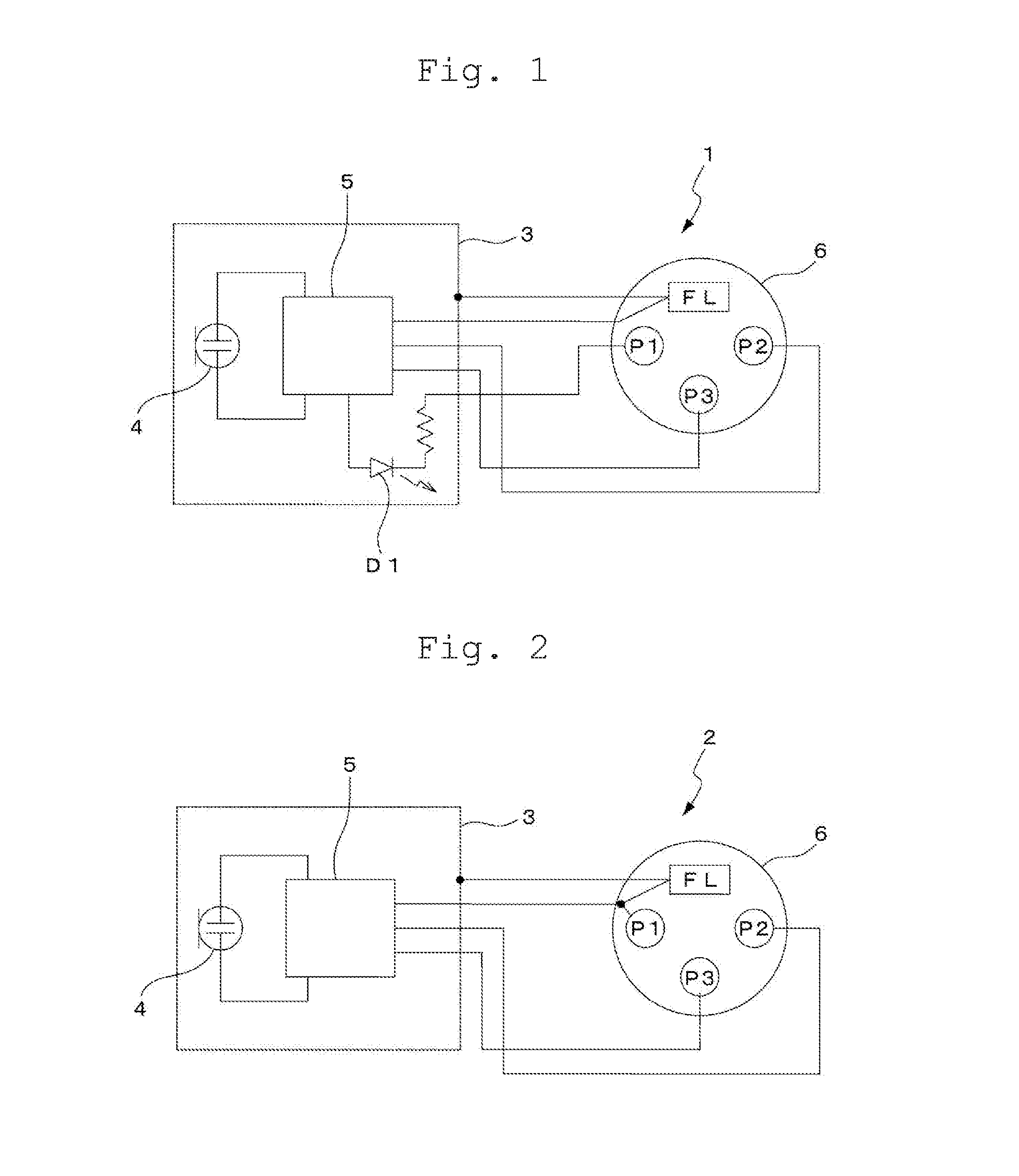
[0034]First, FIG. 1 is a block diagram illustrating a microphone of a first form in which a light emitting body (LED) is mounted as a notifying unit. In the microphone 1 of the first form, a condenser microphone unit 4 and a circuit configuration unit 5 are accommodated in a microphone unit case 3.

[0035]An impedance converter of the condenser microphone unit 4 and a power supply circuit described below, for example, are accommodated in the circuit configuration unit 5. Further, an LED is arranged in the microphone unit case 3, for example, as a light emitting body D1. An anode of the LED is connected to the power supply circuit in the circuit configuration unit 5, and a cathode of the LED is connected to a first pin P1 of an output connector 6.

[0036]The microphone 1 illustrated in FIG. 1 configures a gooseneck-type microphone, for example....


PUM


Abstract

A microphone amplifier unit, to which a microphone of a first form including an LED or a microphone of a second form without including an LED is connected, includes a microphone detecting unit that detects a connection state of the microphone of the first form or the second form based on potential information supplied to a specific terminal pin of a connector. In the microphone amplifier unit, appropriate circuit setting corresponding to functions of the respective microphones is made based on information obtained by the microphone detecting unit. With the configuration, a microphone connecting device that can commonly use the microphone of the first form and the microphone of the second form with a small number of pins is provided.

Description

BACKGROUND OF THE INVENTION[0001]1. Field of the Invention[0002]The present invention realizes control of a notifying unit in a microphone including the notifying unit by remote control, for example, and relates to a microphone connecting device that enables an existing microphone without including the notifying unit to commonly use a balanced-output system of signals.[0003]2. Description of the Related Art[0004]For example, as conference microphones respectively installed on speech tables of conference rooms or tables of conference attendees, gooseneck-type microphones are provided. The gooseneck-type microphones include a stand arm with a long neck made of a flexible pipe that easily enables angle and height adjustment. A microphone unit case which accommodates a microphone unit is attached to a distal portion of the stand arm.[0005]As the gooseneck-type microphones, typically, a small and light condenser microphone is used. A phantom power feeding system which supplies operating ...

Claims


Application Information

Patent Timeline
Patent Type & Authority Applications(United States)
IPC IPC(8): H04R29/00H04R1/02
CPCH04R29/004H04R2420/00H04R1/028
Inventor MATSUMOTO, AKIRA
Owner AUDIO-TECHNICA
Why Eureka
Try Eureka