Systems and methods for diffusing gas into a liquid

a technology of gas diffusion and liquid, applied in the directions of mixing, transportation and packaging, biological water/sewage treatment, etc., can solve the problems of large equipment volume, inability to achieve the effect of reducing the amount of gas in the liquid, etc., to achieve the effect of dense and stable froth

Inactive Publication Date: 2016-09-08
SCHNEIDER JAKOB H +1
View PDF0 Cites 2 Cited by
  • Summary
  • Abstract
  • Description
  • Claims
  • Application Information

AI Technical Summary

Benefits of technology

[0014]While any other suitable ingredient can be added to the liquid stream (e.g., before, during, and / or after it passes through the chamber), in some non-limiting implementations, bacteria (e.g., surfactant-producing and / or non-surfactant-producing bacteria) are added to the stream. In some implementations in which the liquid stream comprises surfactant-producing bacteria, the bacteria produces a surfactant that alters the surface tension of the liquid and allows the mixture of liquid and gas bubbles that exits the chamber to include a relatively dense and stable froth. In contrast, in some implementations in which the liquid stream comprises non-surfactant-producing bacteria, the mixture of liquid and gas bubbles that exits the chamber is relatively free from froth.

Problems solved by technology

While these traditional methods and associated apparatus do achieve aeration, they can be inefficient, requiring long processing times and, hence, large equipment volumes.
The inefficiency associated with some traditional approaches arises largely from the relatively low gas-liquid interfacial area to volumes provided by the equipment.
While such surfactants may act to emulsify contaminants in the liquid, and thereby allow such contaminants to mix and disperse, such surfactants are often toxic to humans, animals, and the environment and can even be non-biodegradable.
Thus, while techniques currently exist that are used to aerate liquids and to treat liquids (such as contaminated water), challenges still exist, including those discussed above.

Method used


Image

  • Systems and methods for diffusing gas into a liquid
  • Systems and methods for diffusing gas into a liquid
  • Systems and methods for diffusing gas into a liquid

Examples


examples

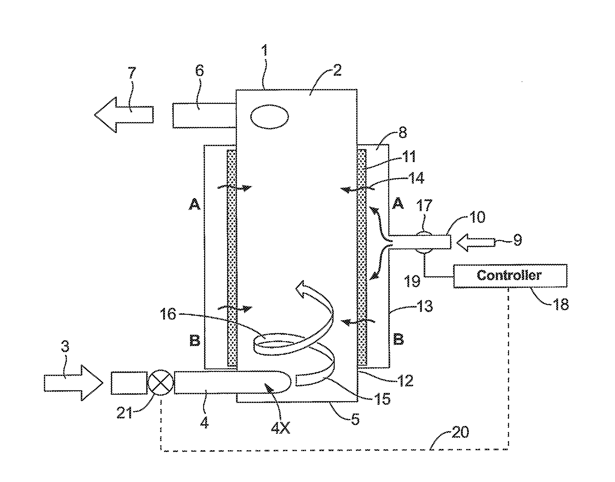
[0058]In a first example, the apparatus 1 was used to aerate a fishpond for 94 hours. In this example, the apparatus pumped approximately 850 cubic meters with a 1:3 water to air ratio. The measurements of the dissolved oxygen in the fishpond were taken every 8 hours. In this regard, the initial 2.76 ppm (mg / l), DO (dissolved oxygen) raised linearly to 6.62 ppm (mg / l) DO at the end of the 94-hour period.

[0059]In a second example, the described apparatus 1 was taken to body of water that was contaminated with ethylene glycol and oil. Upon initial observation of the body of water, it was determined that one or more VOCs were present in the water and emanating a strong odor. When the apparatus 1 was operated using contaminated water (from the body of water) as the liquid that was introduced into the apparatus 1, little to no froth was produced by the apparatus 1. As a result, it was theorized that there was little bacteria present in the contaminated water, and / or that the bacteria in ...


PUM

PropertyMeasurementUnit
mean pore sizeaaaaaaaaaa

Abstract

Systems and methods for diffusing gas into a liquid are disclosed. In some cases, the methods include tangentially introducing a liquid into a cylindrical chamber having a cylindrical inner wall such that the liquid develops a spiral flow. In some cases, gas bubbles are orthogonally introduced into the liquid as the liquid flows through the chamber. In some cases, a flow of the liquid and the gas bubbles is controlled such that a ratio of a liquid flow rate to a gas bubble flow rate does not exceed values which convert non-bacteria enriched, clear water into froth. In such cases, a mixture of the liquid and the gas bubbles to exit the chamber near an output end. While the liquid can include clear water, in some instances, the liquid also includes bacteria (e.g., surfactant-producing or non-surfactant-producing bacteria) and/or bacterial nutrients that allow for improved bioremediation.

Description

RELATED APPLICATION[0001]This is a continuation of U.S. patent application Ser. No. 14 / 293,836 (Attorney Docket No. 16046.21), entitled “SYSTEMS AND METHODS FOR DIFFUSING GAS INTO A LIQUID”, filed on Jun. 2, 2014, Which is a continuation of U.S. patent application Ser. No. 13 / 678,444 (Attorney Docket No. 16046.19), now U.S. Pat. No. 8,740,195, entitled “SYSTEMS AND METHODS FOR DIFFUSING GAS INTO A LIQUID,” filed on Nov. 15, 2012, which is a continuation-in-part of U.S. patent application Ser. No. 13 / 620,069 (Attorney Docket No. 16046.18), now U.S. Pat. No. 8,567,769, entitled “APPARATUS AND METHOD OF DISSOLVING GAS INTO A LIQUID,” filed on Sep. 14, 2012, which is a divisional patent application of U.S. patent application Ser. No. 12 / 162,603 (Attorney Docket No. 16046.5), now U.S. Pat. No. 8,267,381, entitled “APPARATUS AND METHOD OF DISSOLVING GAS INTO A LIQUID,” filed on Jul. 29, 2008, which claims priority to PCT / CA2007 / 000160 and to Canadian Application No. 2534704, filed on Jan....

Claims


Application Information

Patent Timeline
Patent Type & Authority Applications(United States)
IPC IPC(8): C02F3/02B01F5/00B01F5/04B01F3/04
CPCC02F3/02B01F3/04503B01F5/0057B01F5/0476B01F2003/04319C02F2203/006C02F2103/007B01F2215/0052B01F3/04262B01F23/2323B01F25/10B01F25/31421B01F23/232B01F23/23123B01F23/231265B01F2101/305
Inventor SCHNEIDER, JAKOB H.SCHNEIDER, JOSEPH MARK
Owner SCHNEIDER JAKOB H
Why Eureka
Try Eureka