Tissue expander with pectoral attachment

Active Publication Date: 2016-09-15
MENTOR WORLDWIDE
View PDF3 Cites 12 Cited by
  • Summary
  • Abstract
  • Description
  • Claims
  • Application Information

AI Technical Summary

Benefits of technology

[0014]The shell may further include at least one fixation tab coupled to the posterior side of the shell and extending outwardly from the shell, and the attachment flap may further include at

Problems solved by technology

If this mesh or ADM detaches early in the expansion process, it can result in the muscle retracting or recoiling over the top of the tissue expander; an occurrence that is sometimes referred to as “window shading.” This is undesirable in that

Method used


Image

  • Tissue expander with pectoral attachment
  • Tissue expander with pectoral attachment
  • Tissue expander with pectoral attachment

Examples


Embodiment Construction

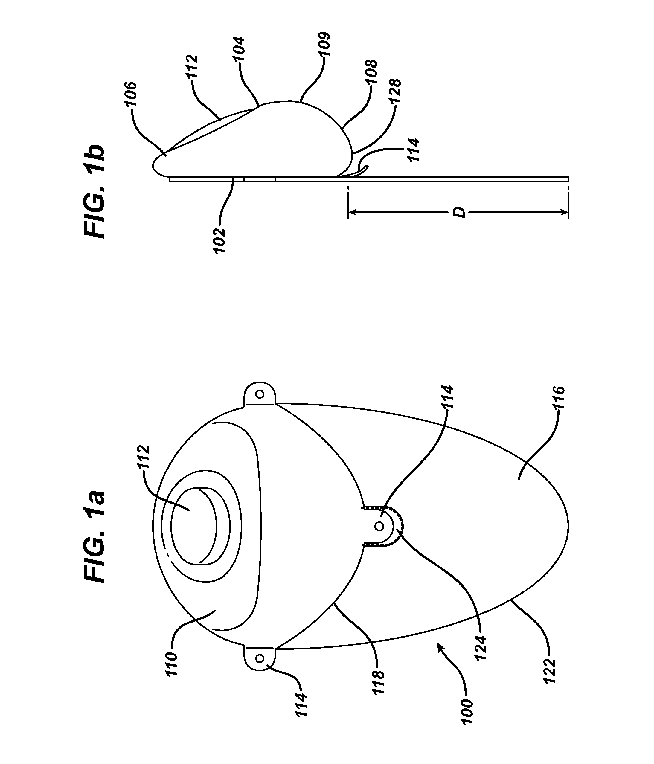
[0022]FIGS. 1a and 1b show front and side views of an exemplary expander 100 according to the present disclosure. The expander has a posterior side 102 that lies substantially flat against the patient's chest wall and an anterior side 104 that faces outward from the chest wall when implanted. The anterior side 104 includes an upper pole region 106 (i.e., the upper portion of the shell when the implant recipient is standing), a lower pole region 108 (i.e., the lower portion of the shell when the implant recipient is standing) and an apex 109 (corresponding to the point at which the nipple would be in a natural breast) separating the upper pole region and the lower pole region. The outer shell 110 of the expander 100 is typically made of a silicone material and includes an injection port or other valve 112 through which saline or another fluid is injected over time into the contained space defined by the outer shell 110. The expander shell 110 can have a smooth or textured surface.

[00...


PUM


Abstract

A mammary tissue expander device including an inflatable shell having an anterior side and a posterior side, the anterior side having an upper pole portion and a lower pole portion meeting at an apex, and an injection port for receiving fluid therethrough to inflate the expander, and a substantially flat attachment flap coupled to the posterior side of the shell, and extending in an inferior direction beyond an inferior edge of the shell by a distance D such that the attachment flap may be extended around the inferior edge and upwards to overlay at least a portion of the anterior side of the shell.

Description

FIELD OF THE INVENTION[0001]The present invention relates generally to the field of implantable tissue expanders, and more particularly to implantable mammary soft tissue expanders having an attachment device for securing the pectoral muscle during expansion.BACKGROUND[0002]Tissue expanders are devices that are implanted beneath the skin and then gradually inflated to stretch the overlying tissue. Such expanders are used to create a pocket for receiving a permanent prosthesis and / or to generate increased skin surface area so that skin can be utilized for grafting or reconstruction.[0003]In the case of mammary implants, tissue expanders are used to create the mammary pocket that will ultimately receive the permanent mammary implant. These expanders are commonly formed of a silicone polymer shell and are implanted in a collapsed state. After implantation, saline or some other fluid is periodically injected into the expander over time, for example through an injection port, until the d...

Claims


Application Information

Patent Timeline
IPC IPC(8): A61B17/00
CPCA61B19/24A61B90/02A61F2/12A61F2250/0059A61F2250/0003A61F2220/0008
Inventor DAVILA, LUIS ALBERTOGRAF, UDO WERNERCANADY, JOHN WESLEY
Owner MENTOR WORLDWIDE
Why Eureka
Try Eureka