Three-dimensional modeling apparatus and manufacturing method
- Summary
- Abstract
- Description
- Claims
- Application Information
AI Technical Summary
Benefits of technology
Problems solved by technology
Method used
Image
Examples
first embodiment
A. First Embodiment
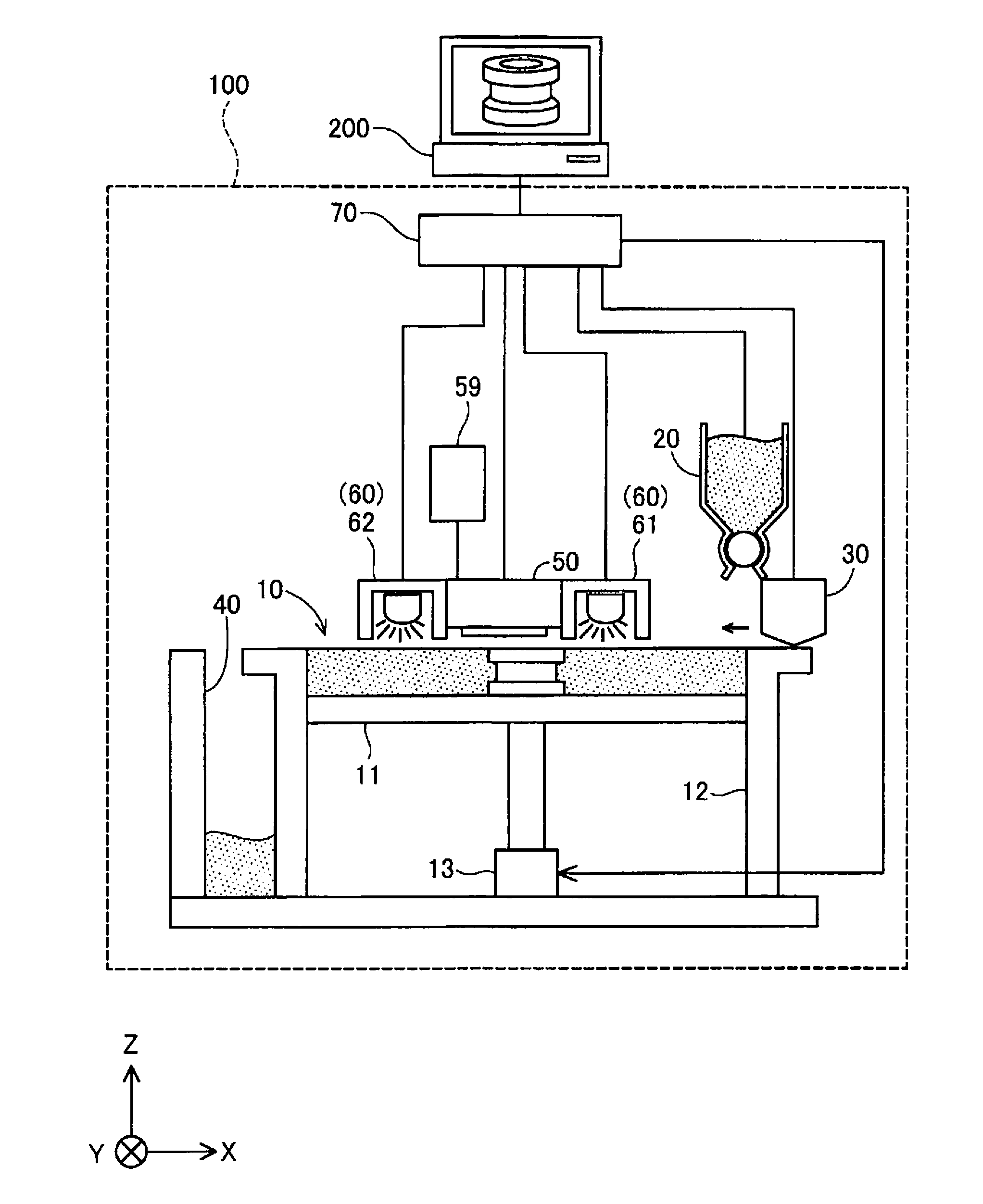
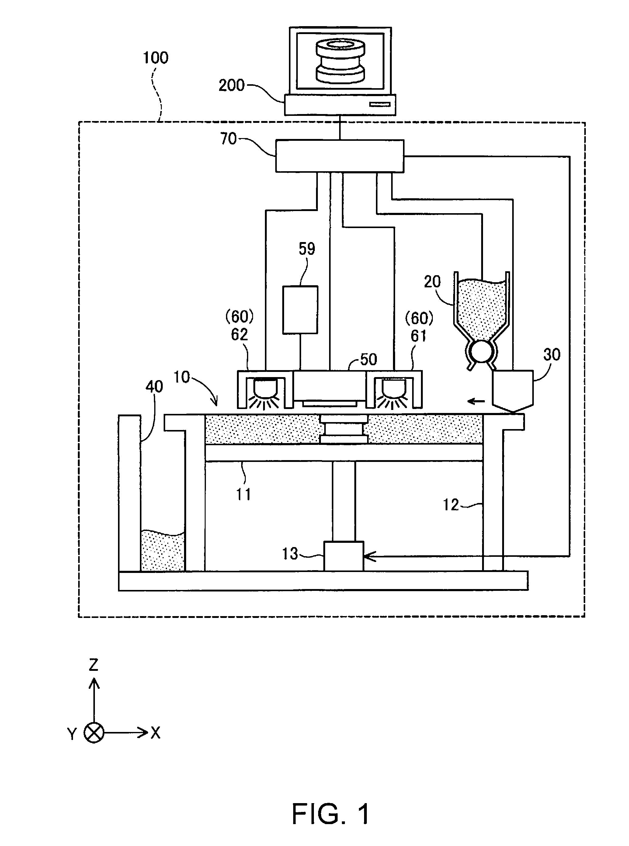
[0034]FIG. 1 is an explanatory diagram showing the schematic configuration of a three-dimensional modeling apparatus as a first embodiment of the invention. A three-dimensional modeling apparatus 100 is provided with a modeling unit 10, a powder supply unit 20, a flattening mechanism 30, a powder collecting unit 40, a head unit 50, a curing energy applying unit 60, and a control unit 70. A computer 200 is connected to the control unit 70. The three-dimensional modeling apparatus 100 and the computer 200 can be collectively regarded as a “three-dimensional modeling apparatus” in a broad sense. In FIG. 1, an X direction, a Y direction and a Z direction that intersect orthogonally to one another are shown. The Z direction is a direction along a vertical direction, and the X direction is a direction along a horizontal direction. The Y direction is a direction perpendicular to the Z direction and the X direction.
[0035]The modeling unit 10 is a tank-shaped structure in ...
second embodiment
B. Second Embodiment
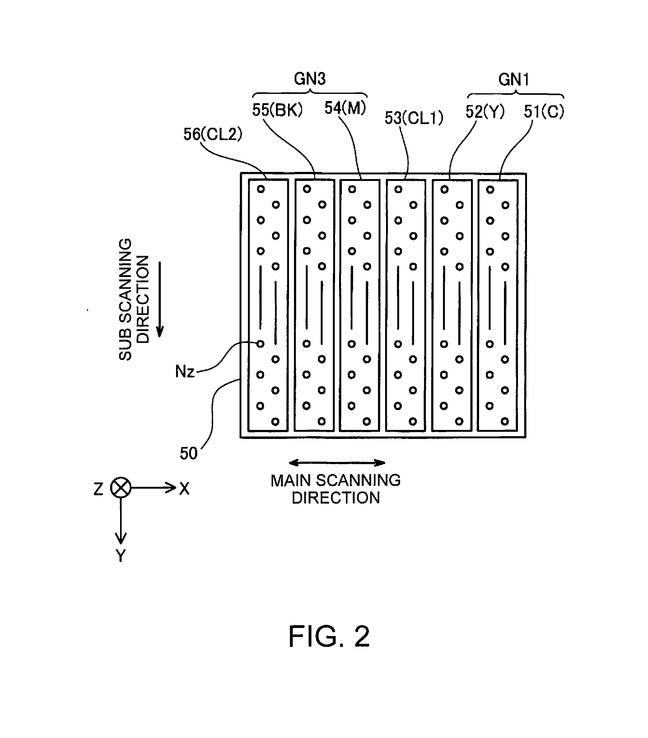
[0068]FIG. 9 is an explanatory diagram showing the schematic configuration of a head unit 50A of a second embodiment. The head unit 50A of the second embodiment has a configuration the same as that of the head unit 50 of the first embodiment, except that the arrangement of the nozzle groups is different. In the head unit 50A, a fifth A nozzle group 51A for discharging droplets of cyan (C) ink, a fifth B nozzle group 52A for discharging droplets of yellow (Y) ink, a fifth C nozzle group 53A for discharging droplets of magenta (M) ink, a fifth D nozzle group 54A for discharging droplets of black (BK) ink, a sixth nozzle group 56A for discharging droplets of the first clear (CL1) ink, and a seventh nozzle group 57A for discharging droplets of the second clear (CL2) ink are aligned in this order in the main scanning direction (X direction). The nozzle groups 51A to 54A are also referred to as “fifth nozzle group GN5” collectively.
[0069]FIGS. 10A to 10F are diagrams s...
third embodiment
C. Third Embodiment
[0075]FIGS. 11A to 11F are diagrams showing an example of unit grilles in a third embodiment. In FIGS. 11A to 11C, a unit grille UG1i and a unit grille UG2j after colored ink and colorless ink were discharged are illustrated, and in FIGS. 11D to 11F, a unit grille UG1k and a unit grille UG2m are illustrated. The unit grilles UG1i to UG2m of the third embodiment are configured such that clear ink is necessarily discharged into the top portion. Note that the unit grilles UG1i to UG2m of the third embodiment do not have sub unit grilles SU. The control unit 70 causes one or more types of colored ink C, M, Y, and BK to be discharged into each of the unit grilles UG1i to UG2m, and then causes the clear ink CL, which is colorless ink, to be discharged into the unit grille UG, thereby filling the spatial volume of the unit grille UG with both the colored ink and the colorless ink, and forming a clear ink layer at the top portion of the unit grille UG.
[0076]A head unit of...
PUM
| Property | Measurement | Unit |
|---|---|---|
| Volume | aaaaa | aaaaa |
Abstract
Description
Claims
Application Information
 - R&D
- Intellectual Property
- Life Sciences
- Materials
- Tech Scout
- Unparalleled Data Quality
- Higher Quality Content
- 60% Fewer Hallucinations
Browse by: Latest US Patents, China's latest patents, Technical Efficacy Thesaurus, Application Domain, Technology Topic, Popular Technical Reports.
© 2025 PatSnap. All rights reserved.Legal|Privacy policy|Modern Slavery Act Transparency Statement|Sitemap|About US| Contact US: help@patsnap.com


