
Flying Booster System

a booster system and booster technology, applied in the field of orbital launch systems, can solve the problems of troublesome detachable process, huge amount of energy needed, and expensive process of launching spacecraft into orbi

Active Publication Date: 2016-09-15
VUONG ANH
View PDF6 Cites 6 Cited by
  • Summary
  • Abstract
  • Description
  • Claims
  • Application Information

AI Technical Summary

Benefits of technology

The present invention is an orbiter launch system that allows for a spacecraft to be launched into orbit from the upper atmosphere using a launch system transporter. The launch system transporter is a reusable vehicle that eliminates the need for bulky external rockets and takes off and lands by tax. The launch system transporter is connected to an orbiter launch assembly that securely carries the spaceorbiter and guides it along a launch system transporter. The launch system transporter provides thrust for the spacecraft and takes off and lands by tax. The launch system is designed to be cost-effective and efficient, with a reduced risk of injury to passengers. The invention also includes a booster rocket connected to the orbiter launch assembly for additional thrust during flight. The launch system is designed to launch a spaceorbiter in mid-air, and a launching trough funnels the exhaust from the spaceorbiter and provides a heat shield to protect the launch system. The invention also includes a reversible seats for passengers and a plurality of roller blocks and locks for securely engaging the spaceorbiter with the launch system. The technical effects of the invention include a reusable launching vehicle that reduces the need for external rockets and a more cost-effective and efficient way to launch spacecraft into orbit.

Problems solved by technology

Launching spacecraft into orbit is an expensive process due to the large amounts of fuel required to generate sufficient thrust.
To lift such a large mass, massive amounts of energy is needed, hence a large amount of fuel or rocket propellant.
However, this can lead to a troublesome process of locating the detachable boosters and retrieving the detachable boosters from the body of water.

Method used


Image

  • Flying Booster System
  • Flying Booster System
  • Flying Booster System

Examples


Embodiment Construction

[0016]All illustrations of the drawings are for the purpose of describing selected versions of the present invention and are not intended to limit the scope of the present invention.

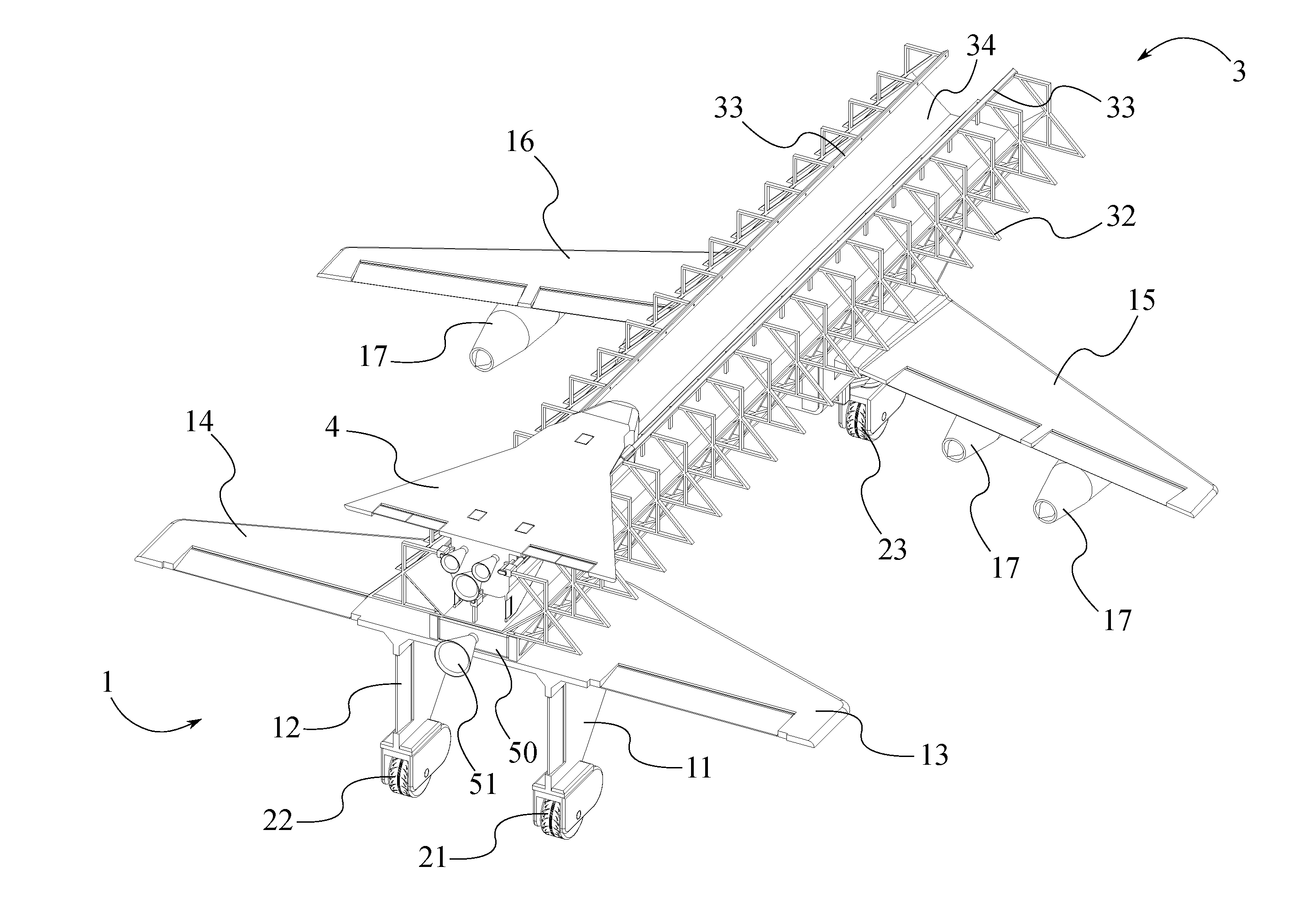
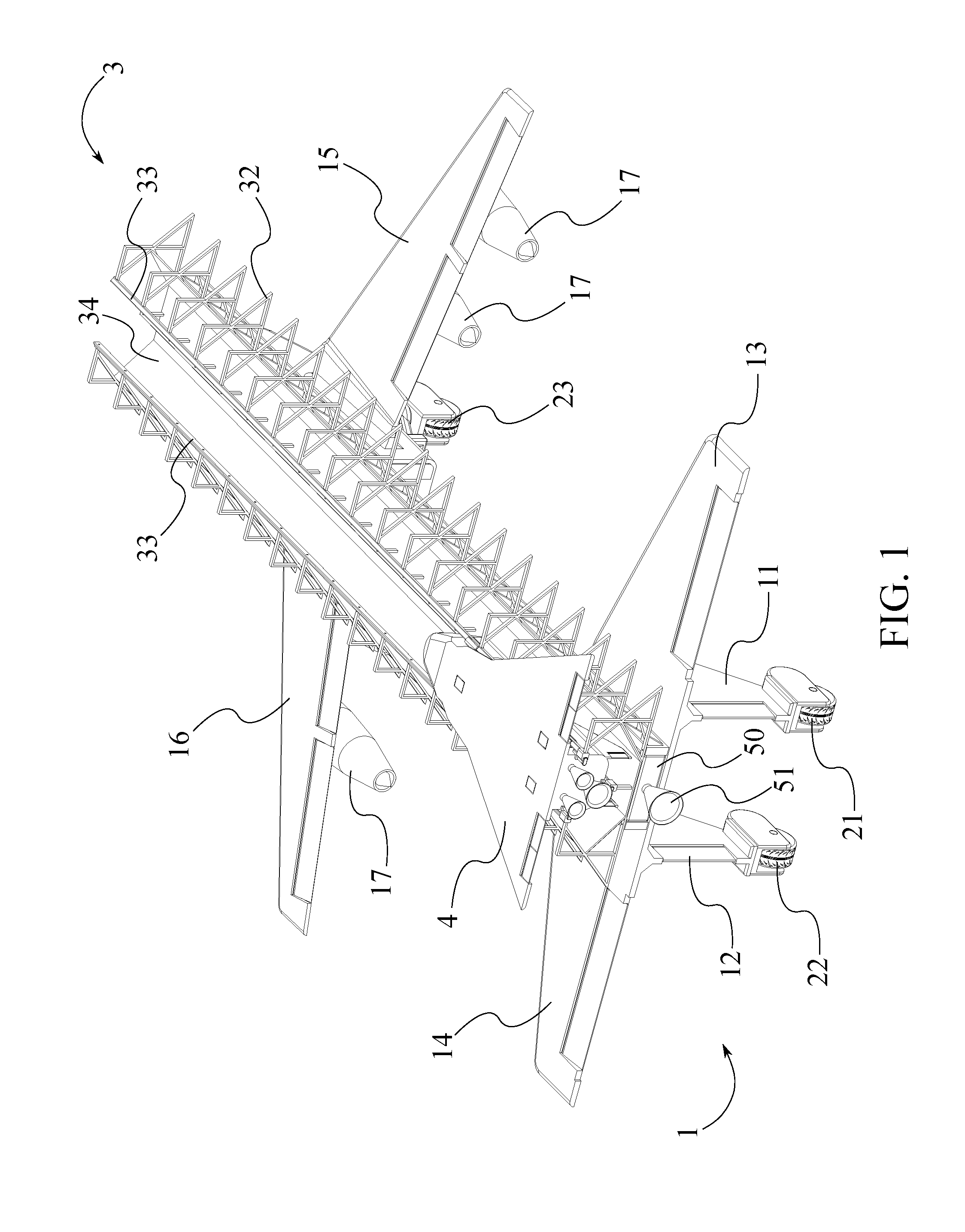
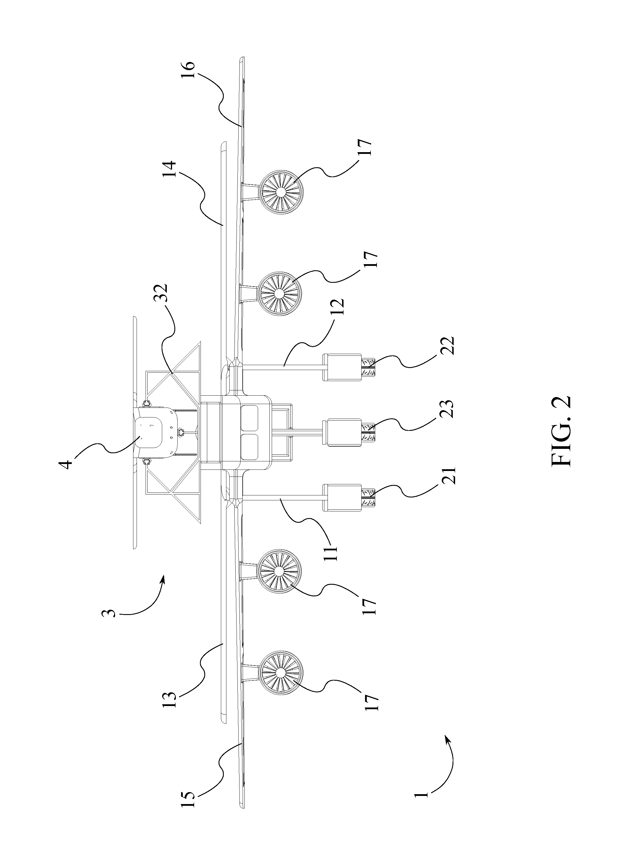
[0017]The present invention is an orbiter launch system for sending a spacecraft into orbit from the upper atmosphere. In reference to FIG. 1, the present invention comprises a launch system transporter 1, an orbiter launch assembly 3, a booster rocket 5, and a space orbiter 4. The launch system transporter 1 provides a means for carrying the space orbiter 4 into the upper atmosphere with assistance from the booster rocket 5, wherein the space orbiter 4 is launched into orbit from the launch system transporter 1. Meanwhile, the orbiter launch assembly 3 provides a means for securing the space orbiter 4 to the launch system transporter 1 and guiding the space orbiter 4 along the launch system transporter 1.

[0018]It is an object of the present invention to provide a reusable launching vehicle (i.e. the lau...


PUM


Abstract

An orbiter launch system for sending a spacecraft into orbit from the upper atmosphere. An orbiter launch assembly is connected to a launch system transporter, wherein the launch system transporter provides lift surfaces for shuttling the orbiter launch assembly and a space orbiter into the upper atmosphere. The space orbiter is slidably engaged with a plurality of stabilization rails of the orbiter launch assembly, wherein the plurality of stabilization rails guides the space orbiter along the orbiter launch assembly when the space orbiter is launched from the launch system transporter. A launching trough funnels exhaust and serves as a heat shield to protect the launch system transporter when the space orbiter is launched. The space orbiter is loaded onto the orbiter launch assembly upside down, wherein a plurality of reversible seats allows passengers to remain sitting upright.

Description

[0001]The current application claims a priority to the U.S. Provisional Patent application Ser. No. 62 / 133,111 filed on Mar. 13, 2015.FIELD OF THE INVENTION[0002]The present invention relates generally to orbital launch systems. More specifically, the present invention provides a launch system transporter for launching a space orbiter in mid-air.BACKGROUND OF THE INVENTION[0003]Launching spacecraft into orbit is an expensive process due to the large amounts of fuel required to generate sufficient thrust. To lift such a large mass, massive amounts of energy is needed, hence a large amount of fuel or rocket propellant. Additionally, most spacecraft launches utilize detachable boosters that carry the spacecraft to a certain altitude before detaching. These detachable boosters then enter freefall and must be collected a refurbished before being used again. Often times the detachable boosters are released over a body of water in order to prevent injury to civilians. However, this can lea...

Claims


Application Information

Patent Timeline
Patent Type & Authority Applications(United States)
IPC IPC(8): B64G1/00B64C1/26B64G1/60B64G1/14
CPCB64G1/005B64G1/14B64C1/26B64G1/60B64D5/00
Inventor VUONG, ANH
Owner VUONG ANH
Learn More