Supercharge Your Innovation With Domain-Expert AI Agents!

Device for Blocking Flow Passage Without Interrupting Flow

a technology of flow passage and device, which is applied in the direction of valve operating means/release devices, diaphragm valves, engine diaphragms, etc., can solve the problems of difficult insertion of blockage bags scratching or damage of blockage bags, and difficulty in insertion into internal flow passages

Active Publication Date: 2016-09-15
WATERWORKS TECH DEV ORG CO LTD
View PDF0 Cites 5 Cited by
  • Summary
  • Abstract
  • Description
  • Claims
  • Application Information

AI Technical Summary

Benefits of technology

The patent text describes a device that blocks a fluid flow in a fluid pipe. The device is designed to prevent the blockage bag from moving downstream in the fluid pipe when there is a risk of the bag coming into contact with burrs or projections on the inner surface of the pipe. This is achieved by providing annular sealing portions on the outer surface of the blockage bag that hold the bag in place and prevent it from moving downstream in the fluid pipe. This design ensures the blockage bag stays in place and prevents fluid leakage, even in situations where there is a risk of the bag coming into contact with potential obstructions in the pipe.

Problems solved by technology

Consequently, the blockage bag may be scratched or damaged, and the insertion of the blockage bag into the internal flow passage via the branch pipe portion and the hole may be difficult in itself.
Therefore, during the insertion of the blockage bag into the internal flow passage of the fluid pipe via the branch pipe portion and the hole, the blockage bag is more likely to, for example, come into contact with a burr on the inner surface of the hole or a projection etc. on the inner surface of the branch pipe portion, and the insertion into the internal flow passage may be more difficult.
Moreover, the blockage bag closing the internal flow passage at the desired blocking position may be deformed or moved to cause a change in the degree of adhesion to an inner circumferential surface of the internal flow passage and thus can no longer sufficiently exhibit the intended closing effect, and accordingly, the stoppage of the fluid may be insufficient.

Method used


Image

  • Device for Blocking Flow Passage Without Interrupting Flow
  • Device for Blocking Flow Passage Without Interrupting Flow
  • Device for Blocking Flow Passage Without Interrupting Flow

Examples


Embodiment Construction

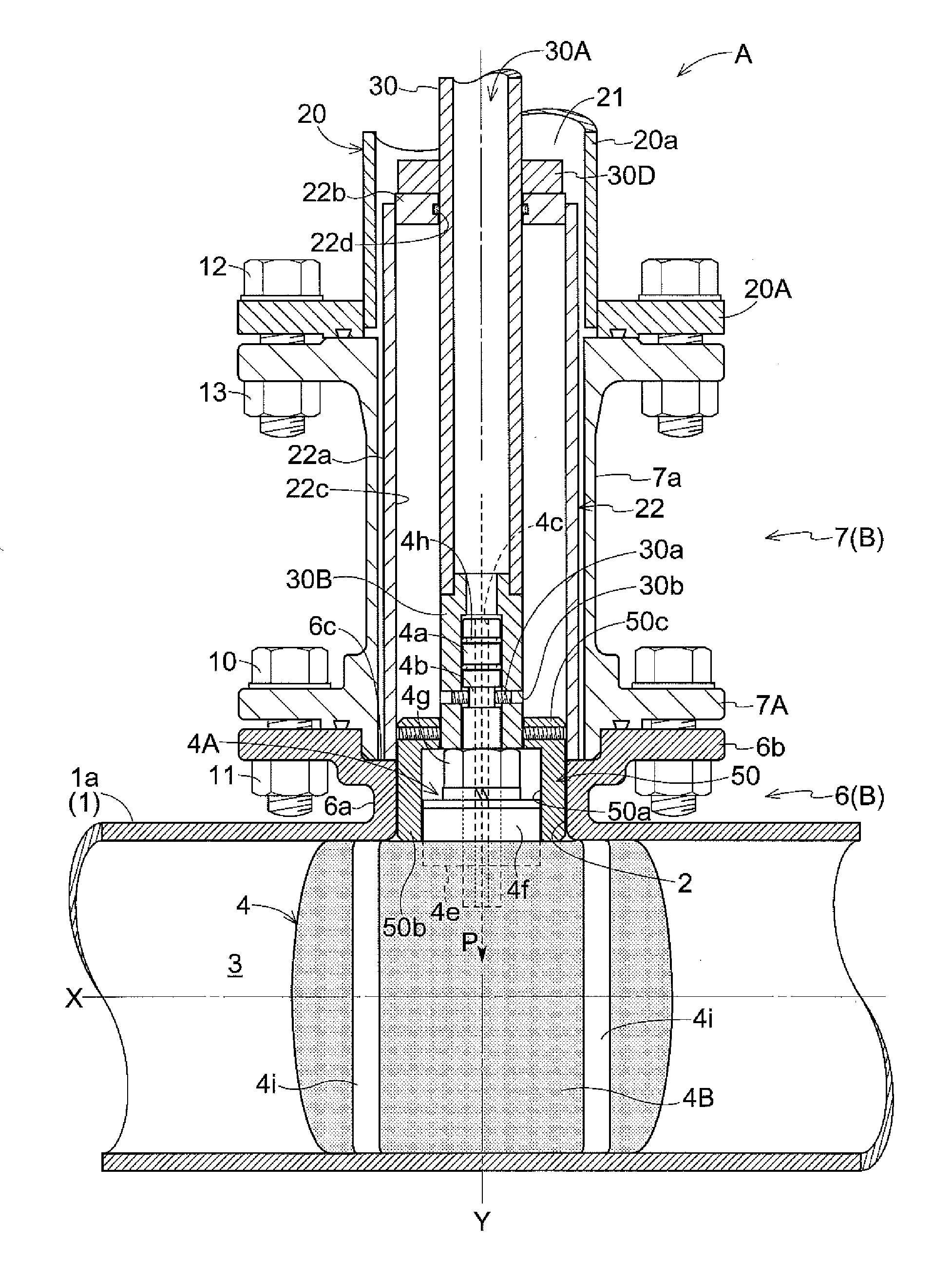
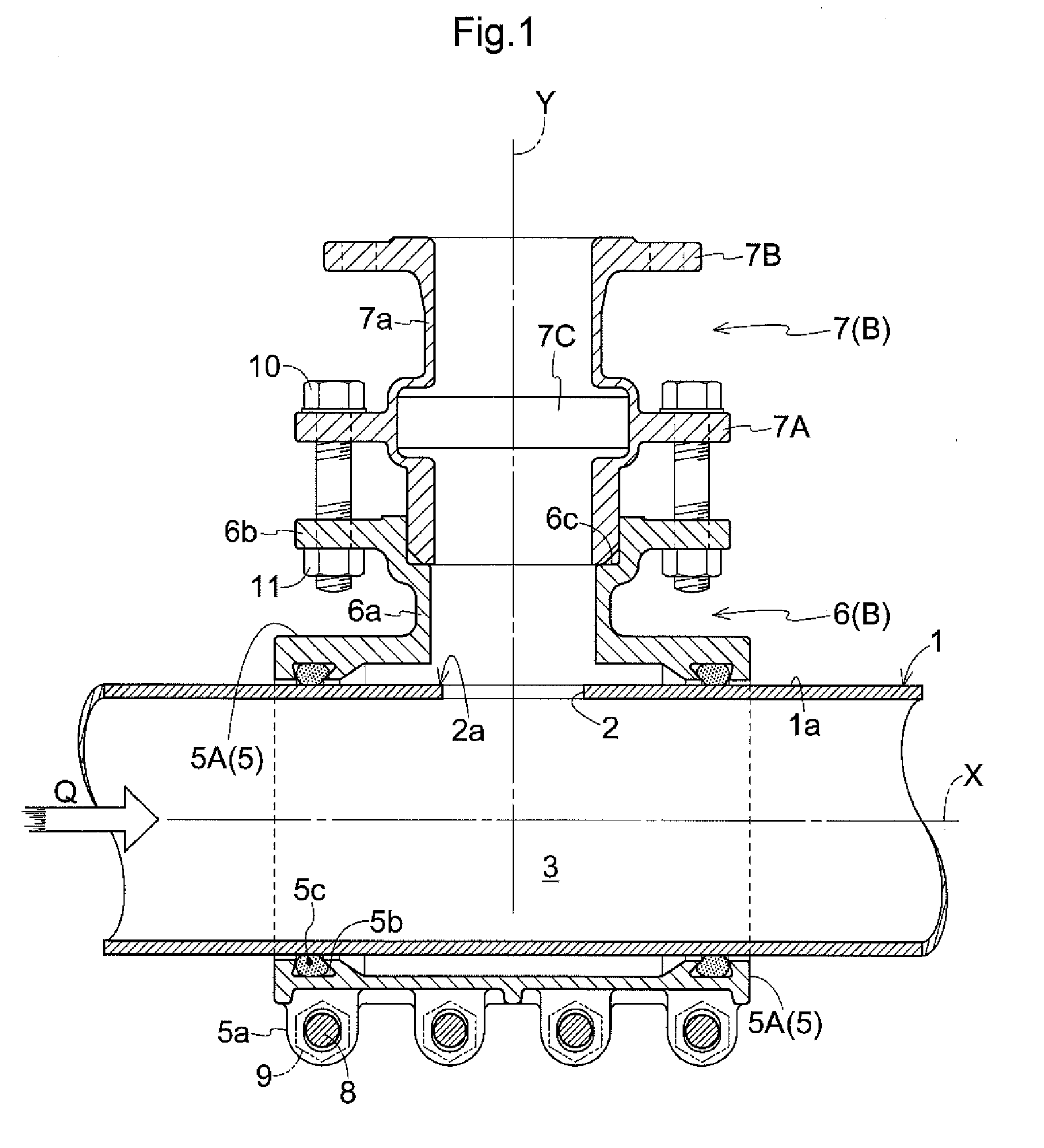
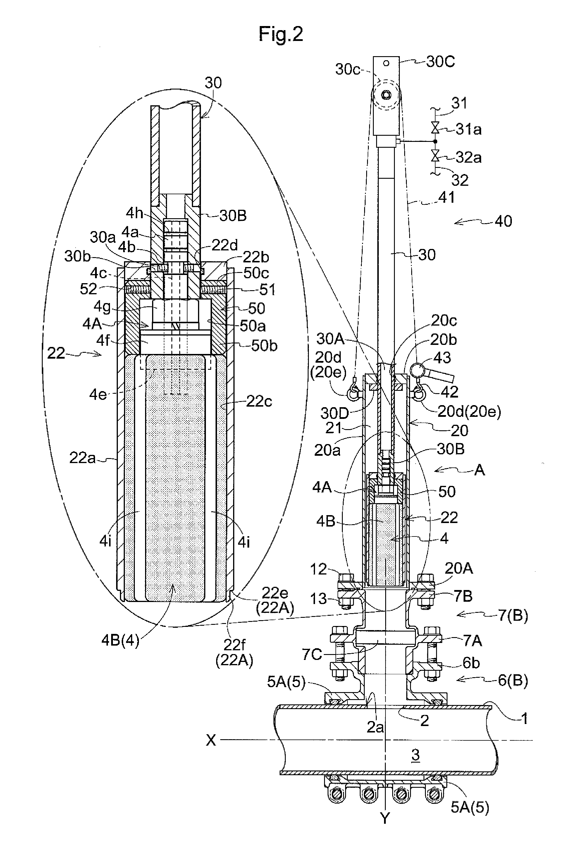
[0081]FIGS. 1 to 10 illustrate a flow passage blocking method that uses a device A for blocking a flow passage without interrupting flow, the device A including a blockage bag 4 that is to be inserted into a water pipe (an example of a fluid pipe) 1 made of cast iron and constituting a part of fluid pipeline, via a hole (an example of a branch port) 2 formed in the water pipe 1, and that is to be deformed and expanded so as to increase in diameter to close an internal flow passage 3 of the water pipe 1, and in which the internal flow passage 3 is closed in an uninterrupted water flow state (an example of an uninterrupted flow state) in which flow of service water (an example of a fluid) Q flowing through the inside of the water pipe 1 is maintained.

[0082]It should be noted that the flow passage blocking method using the above-described flow passage blocking device A is carried out in order to close the internal flow passage 3 of the water pipe 1 in the vicinity of the hole 2 using t...


PUM


Abstract

An insertion guide tube that is inserted into a sealing case and that houses a blockage bag in a reduced-size state can be moved inside the sealing case and inside a branch pipe portion along an axis of the branch pipe portion until the insertion guide tube is brought into an abutting position in which at least a part of a leading end portion of the insertion guide tube abuts against an outer surface-side peripheral edge portion of a branch port on an outer circumferential surface of a fluid pipe. In a state in which the blockage bag is located at a predetermined internal flow passage blocking position, an axis adjustment portion that can make sliding contact with an inner surface of the insertion guide tube is located in a portion corresponding to branch port in a radial direction of the fluid pipe.

Description

TECHNICAL FIELD[0001]This disclosure relates to a device for blocking a flow passage without interrupting flow, the device including a blockage bag that is to be inserted into a fluid pipe via a branch port formed in the fluid pipe and that is to be deformed and expanded so as to increase in diameter to close an internal flow passage of the fluid pipe.RELATED ART[0002]As an example of this type of device for blocking a flow passage without interrupting flow, JP H8-75077A discloses a flow passage blocking device including a blockage bag that is to be inserted into an internal flow passage of a fluid pipe via a branch pipe portion communicating with a hole (an example of the branch port) formed in the fluid pipe and via that hole. This device is configured such that after the blockage bag is inserted into the internal flow passage, the blockage bag can be deformed and expanded so as to increase in diameter by a diameter-increasing fluid being supplied into the blockage bag, and thus c...

Claims


Application Information

Patent Timeline
IPC IPC(8): F16K31/126
CPCF16K31/126F16K7/10F16L55/124F16L55/134
Inventor YAMAMOTO, DAISUKE
Owner WATERWORKS TECH DEV ORG CO LTD
Features
  • R&D
  • Intellectual Property
  • Life Sciences
  • Materials
  • Tech Scout
  • Unparalleled Data Quality
  • Higher Quality Content
  • 60% Fewer Hallucinations
Learn More