Adhesive dam

Active Publication Date: 2013-07-04
STMICROELECTRONICS SRL
View PDF10 Cites 6 Cited by
  • Summary
  • Abstract
  • Description
  • Claims
  • Application Information

AI Technical Summary

Benefits of technology

[0010]A device made according to various embodiments herein includes a circuit substrate and a first component coupled to the circuit substrate by an adhesive. An adhesive dam is positioned sufficiently close to the first component that a portion of the adhesive that couples the first component to the circuit s

Problems solved by technology

However, there are circumstances under which solder is not appropriate, and it becomes necessary to employ alternate means.
However, if solder is emp

Method used


Image

  • Adhesive dam
  • Adhesive dam
  • Adhesive dam

Examples


Embodiment Construction

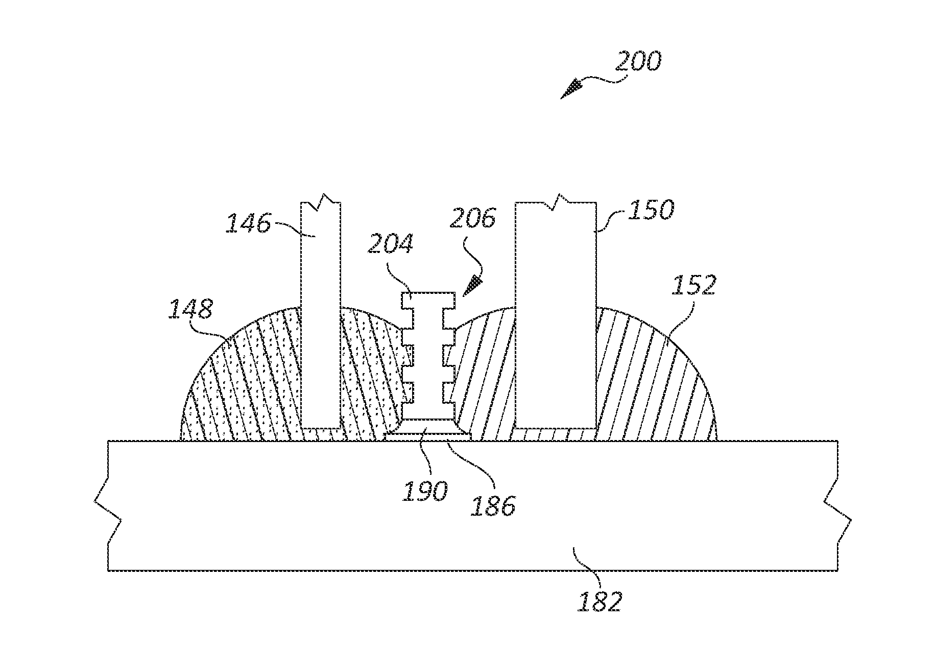
[0023]In selecting an appropriate adhesive for any given application, a number of factors must be considered, including the mechanical strength of the adhesive, the wettability of the material of the parts to be joined, the environment in which the adhesive must function, and the anticipated stress that must be withstood—both in terms of magnitude and vector, relative to the joint. For any given combination of these elements, there will be a minimum volume of adhesive required, and a minimum surface area of contact of the adhesive with each of the parts. If both parts to be joined are highly wettable by an adhesive that has a high mechanical strength, relative to the anticipated stress, and under the anticipated environmental conditions, then the amount of adhesive necessary to make a satisfactory joint may be relatively small. However, as any of the critical factors moves away from a preferred value, the volume and surface area required will generally increase. For example, if the ...


PUM

PropertyMeasurementUnit
Structureaaaaaaaaaa
Lengthaaaaaaaaaa
Shapeaaaaaaaaaa

Abstract

On a circuit substrate on which an adhesive is used to couple electronic or structural components to the substrate, an adhesive dam is positioned to prevent the adhesive from interfering with the operation of the circuit. A contact pad can be provided at a selected location and with a selected shape, and solder deposited on the pad, then reflowed to form the dam. The dam can be a structure soldered to a contact pad, or the dam can be supported at its ends by another structure of the device, so that, at the location where it functions to contain the adhesive, it is not attached to the substrate.

Description

BACKGROUND[0001]1. Technical Field[0002]Embodiments of the present disclosure are related to circuit assembly, and in particular to the use of conductive and nonconductive adhesive to attach components to a circuit board.[0003]2. Description of the Related Art[0004]Typically, components are attached to circuit boards via solder. However, there are circumstances under which solder is not appropriate, and it becomes necessary to employ alternate means. In many cases, adhesives provide certain advantages for use in mounting components, as explained below with reference to FIG. 1.[0005]FIG. 1 is a perspective view of a camera module 100 mounted to a circuit board 102, such as might be used in a cell phone, or other small camera, according to known art. The camera module 100 includes a housing 104, an image sensor chip 106 mounted to a chip carrier 108, a lens 110, and an autofocus module 112. The chip carrier 108 is mounted to the circuit board 102 by a ball grid array comprising a larg...

Claims


Application Information

Patent Timeline
IPC IPC(8): H05K7/06H05K3/30H05K1/16
CPCH05K3/305H05K3/321Y10T29/4913H05K2201/09781H05K2201/09909H05K3/3421Y02P70/50
Inventor LUAN, JING-ENLOOI, HK
Owner STMICROELECTRONICS SRL
Why Eureka
Try Eureka