
Counterweighted backdraft damper blade with improved airflow profile

Active Publication Date: 2016-09-15
T A MORRISON & CO INC
View PDF5 Cites 12 Cited by
  • Summary
  • Abstract
  • Description
  • Claims
  • Application Information

AI Technical Summary

Benefits of technology

The invention is for a blade used in a damper frame for an agricultural machine. The blade has a bull nosed profile which helps to improve air flow and a trough-like feature that helps to smooth out the air flow for better performance. This design makes the air flow through the damper frame more efficient, resulting in better performance of the agricultural machine.

Problems solved by technology

However, this means that some of the force of the air flowing in the outflow direction is always sacrificed in order to maintain the damper blades in the open position, which reduces the airflow of the outflow current.
HVAC systems are typically carefully designed to distribute air evenly about a premises, and this reduction in airflow can have the effect of skewing the pressure distribution to some flow-paths over others, reducing the intended airflow rates to some parts of the premises.
However, this can cause inadvertent leakage in the backdraft direction, resulting in lower efficiency where the backdraft damper is providing thermal protection, and in situations where the backdraft damper is preventing the potential ingress of toxic or noxious gasses can result in a serious risk to occupants of the premises.

Method used


Image

  • Counterweighted backdraft damper blade with improved airflow profile
  • Counterweighted backdraft damper blade with improved airflow profile
  • Counterweighted backdraft damper blade with improved airflow profile

Examples


Embodiment Construction

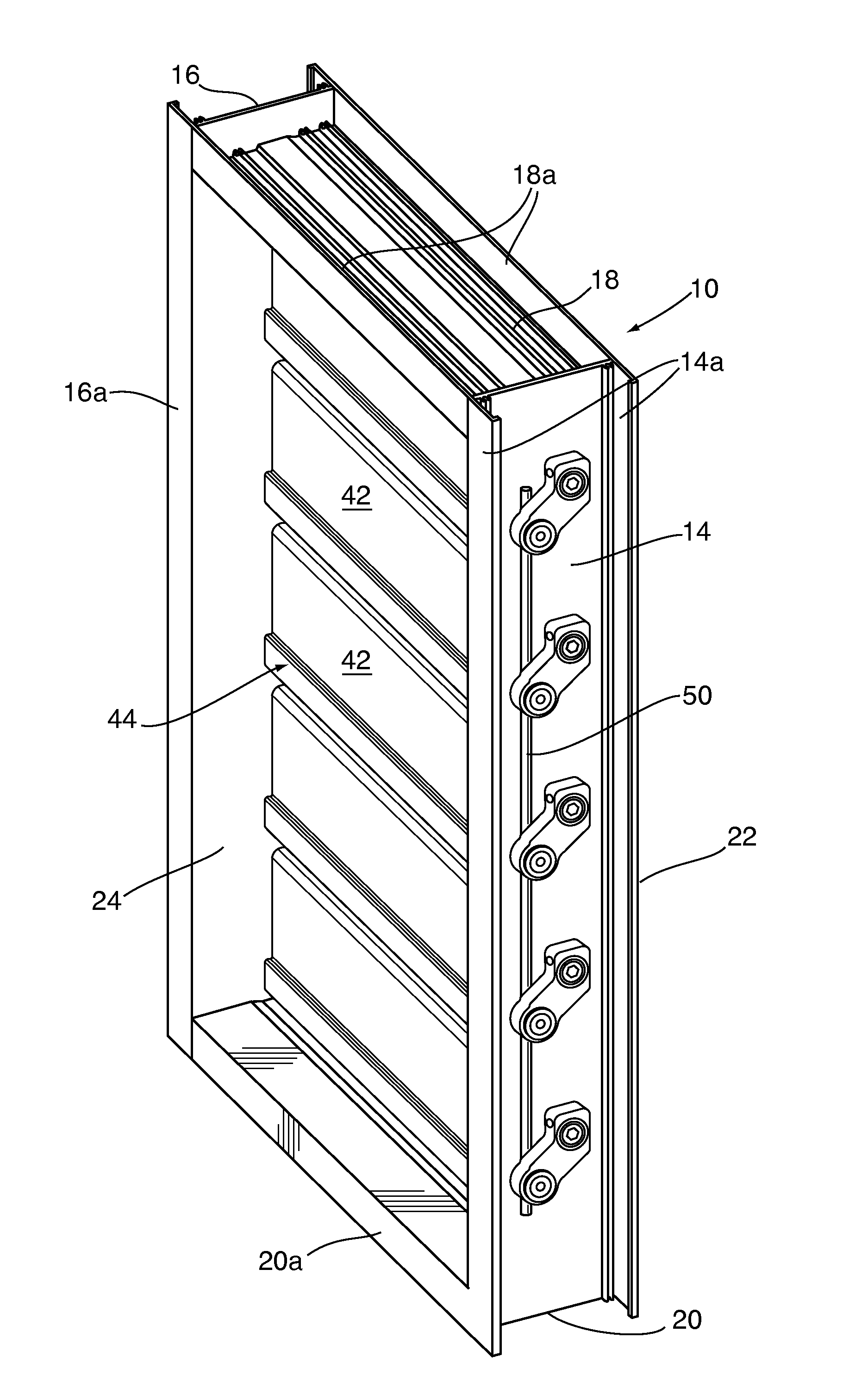
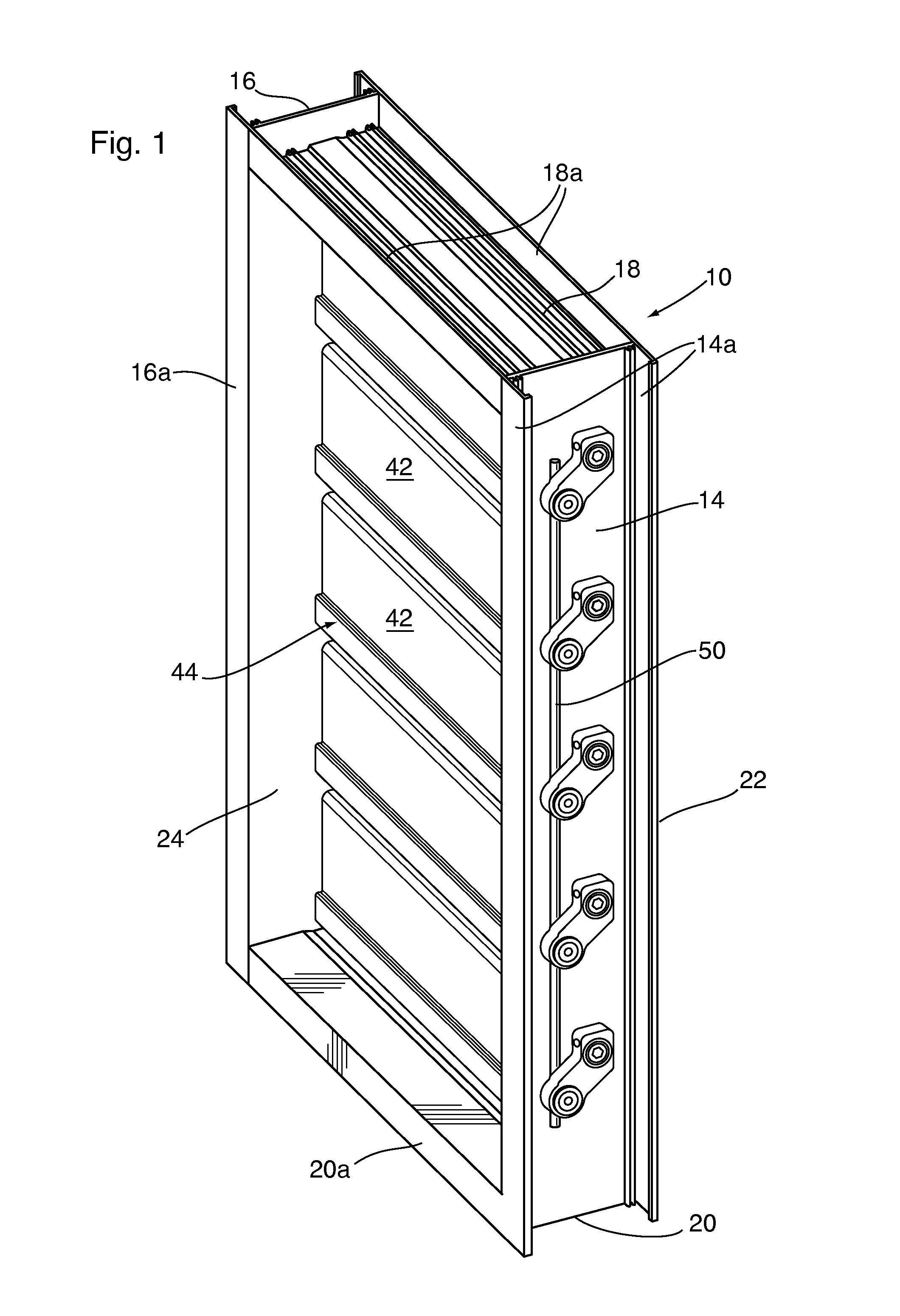
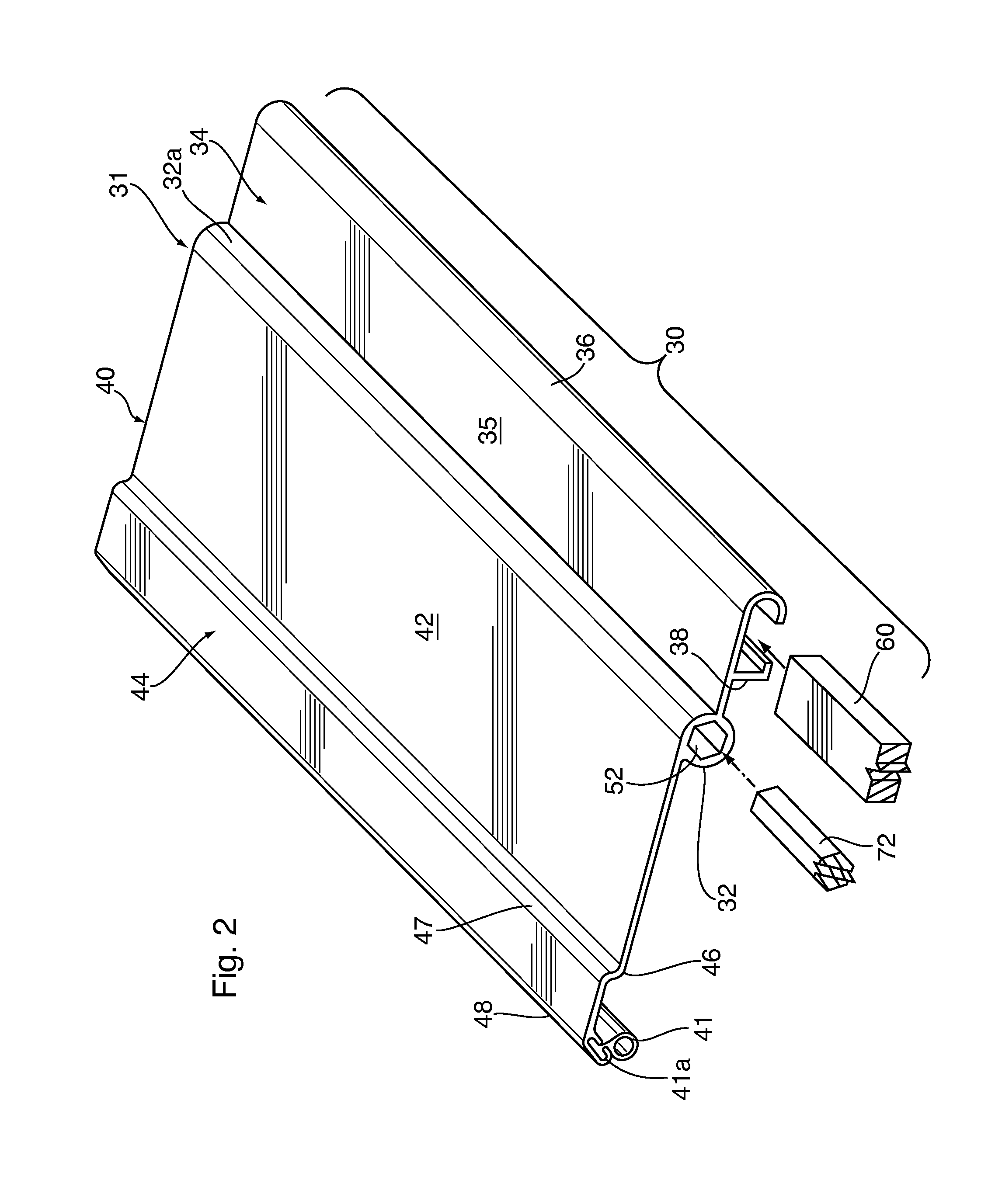
[0014]The invention provides a heavy duty backdraft blade 30. The blade 30 may for example be extruded from aluminium, having a thickness which imparts strength and rigidity. The blade 30 is counterweighted, balancing the blade 30 so that it readily pivots to the open position under the influence of an airflow in the output direction, and pivots to the closed position under the influence of gravity when the airflow ceases.

[0015]In the preferred embodiment the leading edge of the blade 30 has a bull nosed profile, which helps to un-restrict air flow across the blade profile, described in detail below. Also, in the preferred embodiment the downstream portion of the blade 30 has a trough-like feature designed to capture the air flow by creating a static head in the trough, which enables the blade 30 to smooth out the air flow while maintaining a 90 degree opening position in order to maximize the transverse opening through the damper frame.

[0016]The invention thus provides a backdraft ...


PUM


Abstract

A backdraft damper for permitting a flow of air in an outflow direction and preventing the flow of air in a backdraft direction has a frame provided with a transverse opening allowing the passage of air through the frame. One or more blades extend across the frame and are mounted to the frame about a central portion by pivot members, for rotation between open and closed positions. Each blade comprises a blade body having a leading portion upstream of the central portion, the leading portion of the blade body comprising a channel, a trailing portion downstream of the central portion, the trailing portion of the blade having a larger surface area than the leading portion and comprising a seal disposed adjacent to a distal edge of the trailing portion, for sealing against either the leading portion of an adjacent blade or a blade stop projecting from the frame, and a counterweight disposed in the channel, whereby the counterweight balances the blade such that the blade is biased to the closed position by gravity and movable to the open position by the force of air flowing through the frame in the outflow direction.

Description

FIELD OF THE INVENTION[0001]This invention relates to airflow dampers. In particular the invention relates to backdraft dampers.BACKGROUND OF THE INVENTION[0002]Backdraft dampers are used to prevent the backdraft of air in various industrial and commercial heating, ventilating and air conditioning (HVAC) systems.[0003]Such dampers typically comprise an outer frame sized to either fit into a specified opening or to cover a specific opening, in various environments. The damper blades are movable from an open position in which air is permitted to flow through the damper frame in one direction, and a closed position blocking the flow of air through the damper frame in the other direction, in order to prevent the contamination of air within a premises and / or the ingress of thermally unfavourable air (warm or cold) into a thermally controlled premises.[0004]A backdraft damper must work automatically under the force of air, flowing either in the intended (outflow) direction, in which the a...

Claims


Application Information

Patent Timeline
IPC IPC(8): F24F13/14
CPCF24F13/1426F24F2013/1466F24F13/1413F24F13/15
Inventor CHAPPELL, RONALDCAREY, STEPHEN DANE
Owner T A MORRISON & CO INC
Learn More