Fiber optic connector having radio frequency identficiation tag and optical fiber connection device

a technology of radio frequency identification and fiber optic connector, which is applied in the field of fiber optic connectors, can solve the problems of blurring or damage of serial numbers, and affecting the operation of the operator, and achieves the effect of removing the adverse influence of metal materials

Active Publication Date: 2016-09-15
BISON PATENT LICENSING LLC
View PDF2 Cites 5 Cited by
  • Summary
  • Abstract
  • Description
  • Claims
  • Application Information

AI Technical Summary

Benefits of technology

[0033]The fiber optic connector having a radio frequency identification tag according to the above embodiments of the present invention may eliminate the adverse influence of metal material in the fiber optic connector on the read performance of the radio frequency identification tag by disposing the electromagnetism restriction part between the metal holding tube and the radio frequency identification tag. In addition, it is substantially unnecessary to change a size of the fiber optic connector and thus the fiber optic connector may be fitted with a standard connector adaptor for receiving a fiber optic connector.

Problems solved by technology

During each of the above steps, it needs the operator to carefully identifying the serial numbers of the optical fiber and / or the fiber optic connector, thereby easily causing visual fatigue of the operator.
In a situation, the serial numbers may become blurred or damaged due to the severe application condition and may be illegible for the operator.
Also, lighting in the operation field may disadvantageously affect the operator to identify and determine the serial numbers.
Furthermore, it is difficult for the operator to find a misconnection of the optical fibers in the field, and the operator cannot find the misconnection in time.
The above inconvenience will also be encountered in situations such as sequent maintenance of the fiber optic connectors and / or the optical fibers and changes of interconnections by the optical fiber.
Furthermore, the radio frequency signal is very sensitive to metal.
A passive RFID tag cannot normally operate on an object having a metal surface since this will cause an actual readable distance to be far shorter than an expected readable distance.
As a result, the reading efficiency is reduced, misreading will probably occur, or even information in the RFID tag cannot be read at all.

Method used


Image

  • Fiber optic connector having radio frequency identficiation tag and optical fiber connection device
  • Fiber optic connector having radio frequency identficiation tag and optical fiber connection device
  • Fiber optic connector having radio frequency identficiation tag and optical fiber connection device

Examples


Embodiment Construction

[0040]Exemplary embodiments of the present disclosure will be described hereinafter in detail with reference to the attached drawings, wherein the like reference numerals refer to the like elements. The present disclosure may, however, be embodied in many different forms and should not be construed as being limited to the embodiment set forth herein; rather, these embodiments are provided so that the present disclosure will be thorough and complete, and will fully convey the concept of the disclosure to those skilled in the art.

[0041]In the following detailed description, for purposes of explanation, numerous specific details are set forth in order to provide a thorough understanding of the disclosed embodiments. It will be apparent, however, that one or more embodiments may be practiced without these specific details. In other instances, well-known structures and devices are schematically shown in order to simplify the drawing.

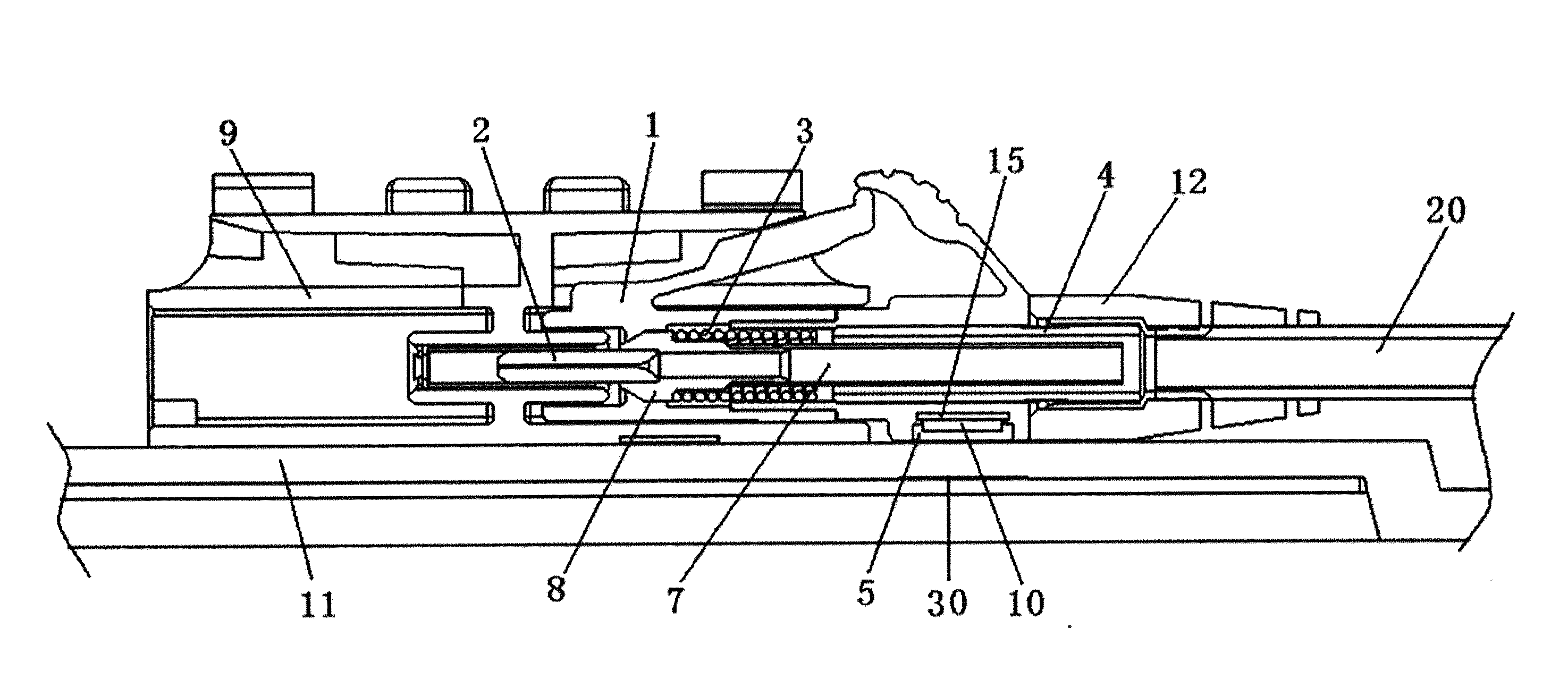
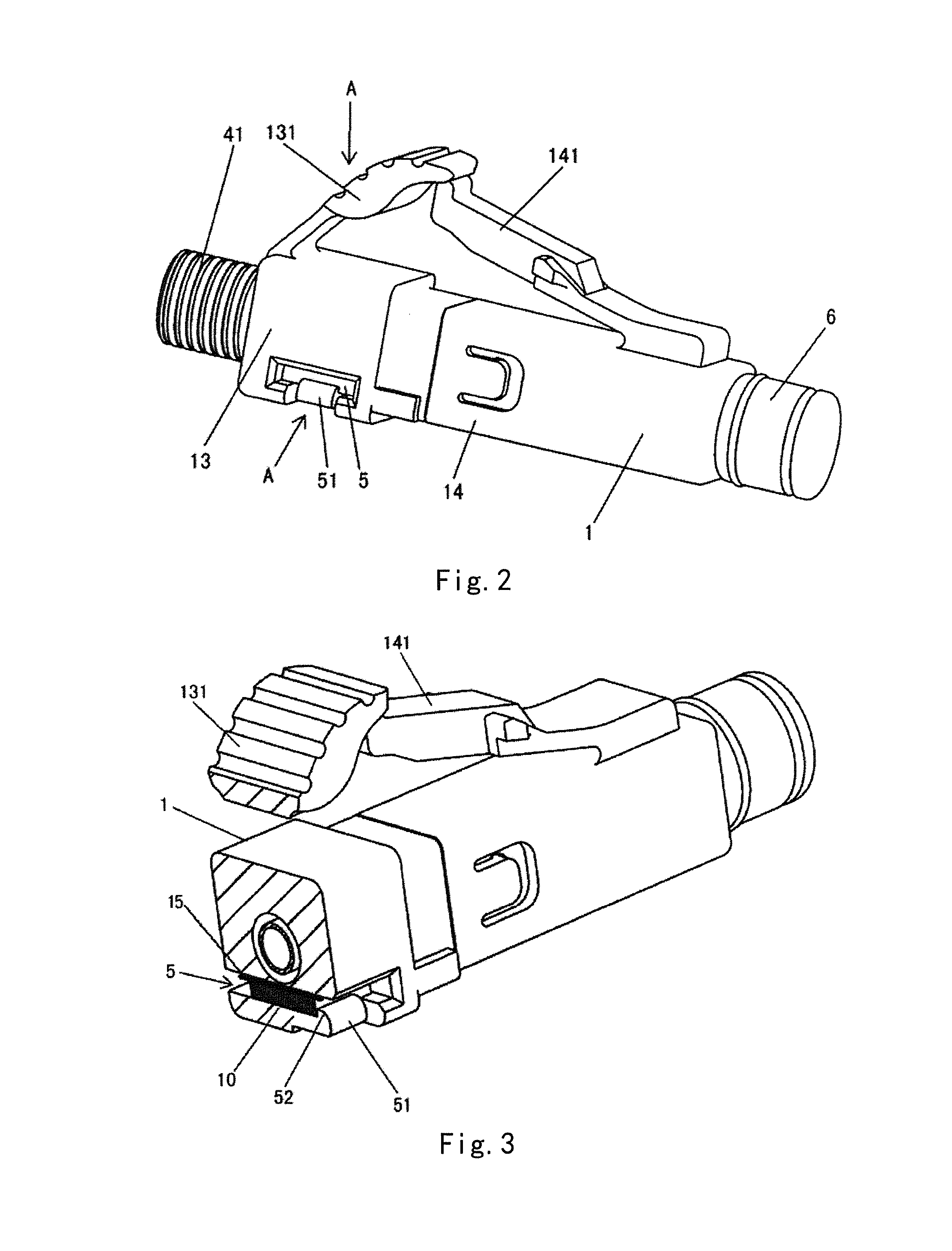
[0042]FIGS. 2-3 show a fiber optic connector, such as a...


PUM


Abstract

A fiber optic connector having a radio frequency identification tag and an optical fiber connection device are disclosed in the embodiments of the present invention. The fiber optic connector comprises: a housing (1); a tail sleeve (4) partly inserted in the housing from a first end of the housing and configured to fix an end of an optical fiber cable (20); a tag receiving portion (5) which is formed in a sidewall of the housing, on a radial outside of the tail sleeve and in which the radio frequency identification tag (10) is disposed; and an electromagnetism restriction part (15) disposed between the tag receiving portion and the tail sleeve to restrict an electromagnetic influence of the tail sleeve made of a metal material on the radio frequency identification tag. The adverse influence of metal material in the fiber optic connector on the read performance of the radio frequency identification tag may be eliminated by disposing the electromagnetism restriction part between the metal holding tube and the radio frequency identification tag.

Description

CROSS-REFERENCE TO RELATED APPLICATION[0001]This application claims the benefit of Chinese Patent Application No. 201320631508.2 filed on Oct. 12, 2013 in the State Intellectual Property Office of China, the whole disclosure of which is incorporated herein by reference.BACKGROUND OF THE INVENTION[0002]1. Field of the Invention[0003]Embodiments of the present invention relates to an fiber optic connector, and more particularly, to an fiber optic connector having a radio frequency identification (RFID) tag and an optical fiber connection device having the fiber optic connector.[0004]2. Description of the Related Art[0005]In an optical fiber communication system, a fiber optic connector and an optical fiber adaptor are used to perform coupling, distributing or transferring among different optical fibers or pigtail fibers, and each of the fibers or pigtail fibers is coupled to the respective fiber optic connector.[0006]In the prior art, during connecting optical fibers in an optical fib...

Claims


Application Information

Patent Timeline
Patent Type & Authority Applications(United States)
IPC IPC(8): G02B6/38
CPCG02B6/3895G02B6/3887G02B6/3825G02B6/3821G02B6/3874G02B6/3849G06K19/07771
Inventor ZHANG, WEILITONG, ZHAOYANG
Owner BISON PATENT LICENSING LLC
Why Eureka
Try Eureka