Head-mounted display

a display and head technology, applied in the field of head-mounted displays, can solve the problems of the wearability of the head-mounted display, and the user who uses glasses for visual acuity correction has had a problem with the head-mounted display. achieve the effect of simple configuration

Active Publication Date: 2016-09-15
SONY CORP
View PDF4 Cites 54 Cited by
  • Summary
  • Abstract
  • Description
  • Claims
  • Application Information

AI Technical Summary

Benefits of technology

[0032]As described above, according to the present technology, it is possible to hold glasses for visual acuity correction by a simple configuration.
[0033]It should be noted that the effects described herein are not necessarily limited and any effect described in this disclosure may be produced.

Problems solved by technology

Therefore, for example, a user who uses glasses for visual acuity correction has had a problem in wearability of the HMD because of little space for arranging the glasses.

Method used


Image

  • Head-mounted display
  • Head-mounted display
  • Head-mounted display

Examples


first embodiment

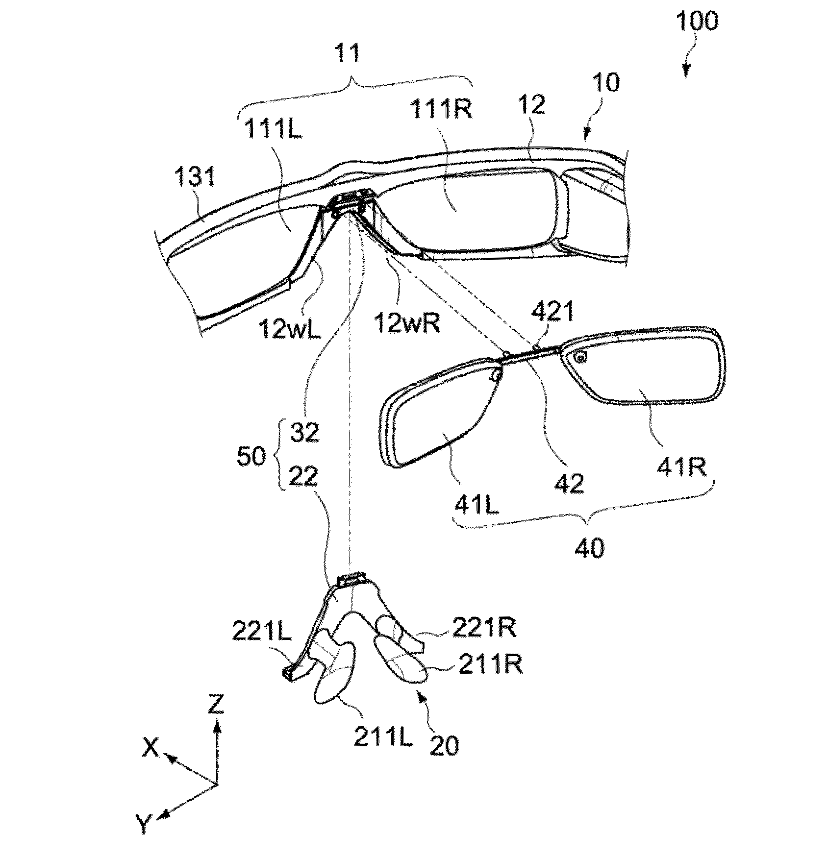
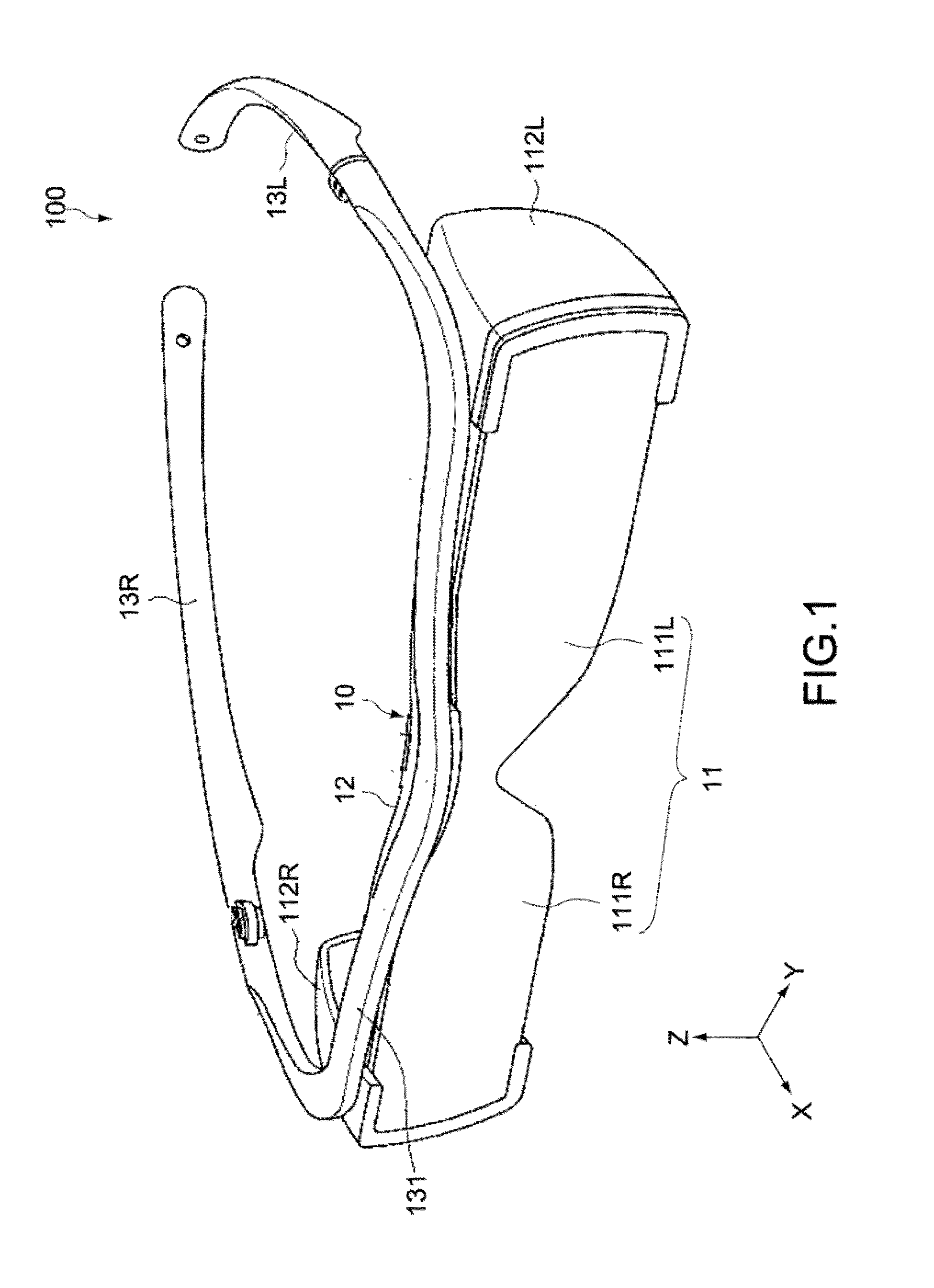
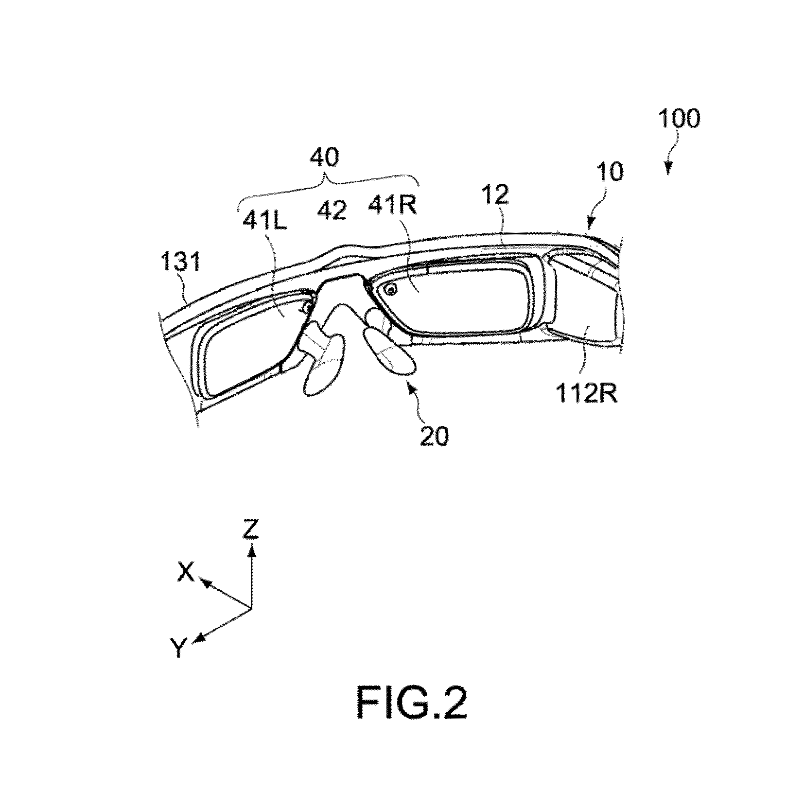
[0044]FIGS. 1 and 2 each show a head-mounted display according to a first embodiment of the present technology. FIG. 1 is an overall perspective view when viewed from the front side, and FIG. 2 is a perspective view of a main part when viewed from the back side. In each figure, X, Y, and Z axes are three axial directions orthogonal to one another, and the X axis represents a front and back direction, the Y axis represents a right and left direction, and the Z axis represents a height direction.

Configuration of Head-Mounted Display

[0045]A head-mounted display 100 of this embodiment includes a main body 10 and a nose pad 20.

Main Body

[0046]The main body 10 includes a display portion 11 capable of presenting an image to a user and is configured to be mountable on the head of the user. Specifically, the main body 10 includes the display portion 11, a frame portion 12 that supports the display portion 11, and temple portions 13R and 13L that are fixed to the frame portion 12.

[0047]The dis...

second embodiment

[0084]FIG. 8 is a schematic plan view showing a configuration of a head-mounted display according to a second embodiment of the present technology. Hereinafter, a configuration different from the first embodiment will be mainly described, and a configuration similar to the embodiment described above will be denoted by similar reference symbols and description thereof will be omitted or simplified.

[0085]A head-mounted display 200 of this embodiment includes a main body 10 including a display portion 11, and correction glasses 240. This embodiment is different from the first embodiment described above in that two lens portions 41 R and 41 L of the correction glasses 240 are disposed on the outer side (front side) of the display portion 11.

[0086]FIG. 9 is a perspective view showing a configuration example of the correction glasses 240. The correction glasses 240 include the two lens portions 41R and 41L, a bridge portion 42, and a suspended portion 43.

[0087]The two lens portions 41R an...


PUM


Abstract

[Object]To provide a head-mounted display that is capable of holding glasses for visual acuity correction by a simple configuration.
[Solving Means]A head-mounted display according to an embodiment of the present technology includes a main body, a nose pad, and a holding mechanism. The main body includes a display portion capable of presenting an image to a user and is configured to be mountable on a head of the user. The nose pad is configured to be attachable to and detachable from the main body. The holding mechanism is configured to be capable of holding correction glasses between the main body and the nose pad mounted to the main body, the correction glasses facing the display portion.

Description

TECHNICAL FIELD[0001]The present technology relates to a head-mounted display that is mounted on the head of a user for use.BACKGROUND ART[0002]There is known a head-mounted display (hereinafter, also referred to as HMD) that is configured to be mounted on the head of a user to present an image to the individual user by a display disposed in front of the eyes of the user.[0003]In order to achieve visibility of images, an improved design quality, downsizing, or the like, the HMD is designed such that a large space is not generated between the face of a user and the HMD when the user wears the HMD. Therefore, for example, a user who uses glasses for visual acuity correction has had a problem in wearability of the HMD because of little space for arranging the glasses. For that reason, there is proposed an HMD that is configured such that a correction lens for correcting visual acuity can be attached thereto (see Patent Document 1).[0004]Patent Document 1: Japanese Patent Application La...

Claims


Application Information

Patent Timeline
Patent Type & Authority Applications(United States)
IPC IPC(8): G02C9/00G02C5/12G02B27/01G02C11/00
CPCG02C9/00G02C11/10G02C5/126G02B2027/0158G02B2027/0178G02B2027/0156G02B27/0176G02B27/0172G02C5/124H04N5/64G02C5/12G02C9/04
Inventor YOSHIDA, TAKAAKI
Owner SONY CORP
Why Eureka
Try Eureka